This thread has been locked.

If you have a related question, please click the "Ask a related question" button in the top right corner. The newly created question will be automatically linked to this question.

PSPICE-FOR-TI: Meaning of PSpice for TI supports a minimum of one and maximum of three traces

Part Number: PSPICE-FOR-TI
Other Parts Discussed in Thread: TPS61165

I can simlulate with TI's genuine libs. However when I have imported a 3th party lib (en.ST_power_schottky_diodes_pspice_models_v6.zip), I got this message:

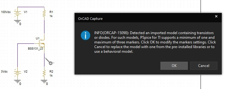
ERROR(ORPSIM-16583): Detected an imported model containing transistors or diodes. For such models, PSpice for TI supports a minimum of one and maximum of three traces. Reduce the number of traces and simulate again.

ERROR(ORPSIM-16583): Detected an imported model containing transistors or diodes
Run aborted

What does it mean, and how can I avoid it?

I saw this ticket, where it was a problem, but no reason was determined: (7) [Resolved] PSPICE-FOR-TI: Simulation error Pspice for Ti - Simulation, hardware & system design tools forum - Simulation, hardware & system design tools - TI E2E support forums

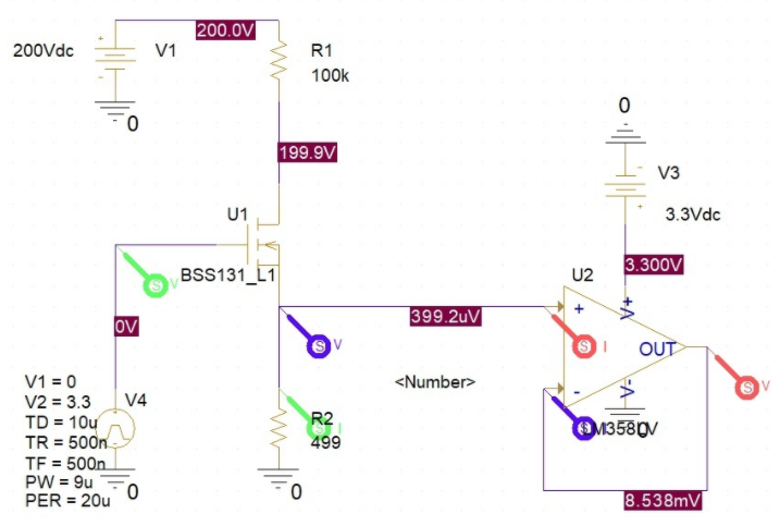
I can run the simulation if I use measuring markers (1, 2 or 3). It seems up to 3pcs measure points could be used. If no marker used, I got this error. If number of markers are above 3, then I can not select them in charts, but simulation runs fine.

Marker (voltage tip) looks like this: 

Other markers is exist: current, power tip etc...

If it is an implemented constraint in PSpice for TI as free edition software tool. But I see here and on the internet that people could use more then 3pcs markers and simulation runs with 3th party libs too.

Unfortunately David only wrote this: "i somehow managed to get the simulation running" What did he do?

It seems a lot of markers are used and simulation is running fine. So I don't understand what this error message mean?

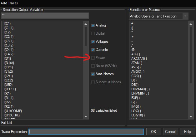
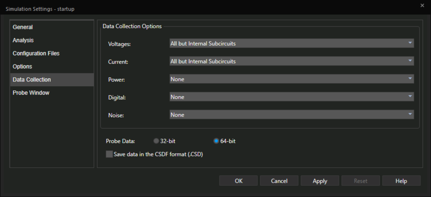
What is the meaning of PSpice for TI supports a minimum of one and maximum of three traces?

What is the backdoor to avoid this error message in case of using external 3th party libs/component?

What is the difference(correlation) between traces and measuing markers?

PS: don't forget I can run the simulation in case of external lib, if I place 1, 2 or 3pcs measuring marker onto the schematic.

Attila

  • Attila,

    None of your screenshots came through. This forum does not support pasted image. Please save them to a file then use the paperclip icon to insert them.

    The 3-probe limit is explained in this FAQ: https://e2e.ti.com/support/tools/sim-hw-system-design/f/234/t/969665.

    I cannot answer your question about another user's comment.

    Measure marker tells the simulator what signal (voltage, current, etc) to save into the result file. Trace is what you plot in the waveform viewer. You cannot plot something that was not saved.

    Regards,
    JC

  • Hi JC,

    Thanks for attention.

    For better readability, missed pictures are inserted now (from top to bottom). It is very interesting, that David has used more than 3pcs probes on design, when Davaid's ticket talkes about using of external component and its errors.

    #1:

    #2:

    #3:

    More questions:

    1. How could I use colorised probes as picture3 above?

    I have grey markers(probes) on schematic. Take a look to picture2. 

    2. What is the reason, that I can not select W-probes (for power dissipation) under genuine TI's reference design at plots, when no external lib used?

    I'v downloaded and used TPS61165 reference design. I can place V/I/W-probes, but I can not select W-probes at plots. The Power checkbox is inactive.

    Without manual placed probes, I and V signals are only available for plotting without any restriction.

    It seems as restriction of free edition.

    When I don't use external components (e.g. reference design), then there are available design generated signals without probes (e.g. V(U2:OUT), I(U2:+). But, there is not available signals for power dissipation. I can not select power measurement probe (W-probe) signals.

    When I load an external component into this design (e.g. replacing the schottky diode), then it seems, the design steps into restriction mode, the auto generated signals are missed (e.g. V(U2:OUT), I(U2:+), and only the placed probes are available for selection. The power probes are available next to other V/I-probes.

    Attila

  • Attila,

    Again, I cannot comment on another user's design. I have no knowledge of that. This is a public forum so you can ask him directly in the related thread, or send him a friendship request.

    The signals to be saved is in the simulator settings, like all other Spice simulators. You can see that in the sim profile, under "Data collection". If you don't save any power signal here, they won't be saved and you get the gray'ed out checkbox:

    After you added the 3rd party diode model, the data collection is determined by the probes. If you place a power probe, the corresponding power signal will be saved and you can plot it.

    Thanks,
    JC

  • Hi JC,

    You are right. It is working now.

    The problem was, that TI's reference project data collection was only predefined for V and I (not for W). But when I used to 3th party model, then PSpice automatic overwitten this project parameter and enabled to W log too.

    It was not clear for me.

    Attila