This thread has been locked.

If you have a related question, please click the "Ask a related question" button in the top right corner. The newly created question will be automatically linked to this question.

PSPICE-FOR-TI: Simulation error Pspice for Ti

Part Number: PSPICE-FOR-TI
Other Parts Discussed in Thread: LM358LV, TLV9052, OPA197

Dear *,

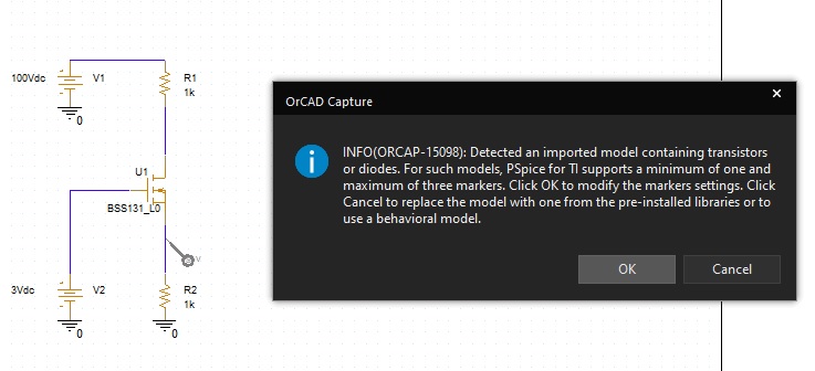
i tying to run simulation with BSS131 mosfet.

i imported the model to PSPICE FOR TI, and in Edit simulation profile -> configuration files -> library added the .lib to design

when i run the dc simulation i get this error:

----------------------------------------------------------------------------------------------------------------------------------------

**** 09/09/20 12:24:12 ******* PSpice 17.4.0 (Nov 2018) ******* ID# 0 ********

** Profile: "SCHEMATIC1-DcSim" [ D:\Simulation\Pspice\LedMosfetVoltage\LedMosfetVoltage-PSpiceFiles\S


**** CIRCUIT DESCRIPTION


******************************************************************************


** Creating circuit file "DcSim.cir"
** WARNING: THIS AUTOMATICALLY GENERATED FILE MAY BE OVERWRITTEN BY SUBSEQUENT SIMULATIONS

*Libraries:
* Profile Libraries :
* Local Libraries :
.LIB "../../../lib/infineon-simulationmodel_optimos_powermosfet_pspice_240v_400v_600v_800v_n-channel-sm-v01_00-en/n_channel_small_s"
+ "ignal_240v_250v_400v_600v.lib"
* From [PSPICE NETLIST] section of C:\Users\David\AppData\Roaming\SPB_Data\cdssetup\OrCAD_PSpiceTIPSpice_Install\17.4.0\PSpice.ini file:

ERROR(ORPSIM-16276): Simulation cannot be completed because library ../../../lib/infineon-simulationmodel_optimos_powermosfet_pspice_240v_400v_600v_800v_n-channel-sm-v01_00-en/n_channel_small_signal_240v_250v_400v_600v.lib
is not available.
.lib "nom_pspti.lib"
.lib "nom.lib"

*Analysis directives:
.DC LIN V_V1 0 240 1
.OPTIONS ADVCONV
.PROBE64 V(alias(*)) I(alias(*)) W(alias(*)) D(alias(*)) NOISE(alias(*))
.INC "..\SCHEMATIC1.net"

**** INCLUDING SCHEMATIC1.net ****
* source LEDMOSFETVOLTAGE
X_U1 N00166 N00174 N00170 BSS131_L0
R_R1 N00166 N00162 1k TC=0,0
R_R2 0 N00170 1k TC=0,0
V_V1 N00162 0 200Vdc
V_V2 N00174 0 3Vdc

**** RESUMING DcSim.cir ****
.END

Best Regards,

David.

  • i slowed the first error by re-adding the .lib file and now i got:

    --------------- INFO(ORPROBE-3209): Simulation Profile: SCHEMATIC1-DcSim ---------------
    INFO(ORPROBE-3183): Simulation running...
    ** Profile: "SCHEMATIC1-DcSim" [ D:\Simulation\Pspice\LedMosfetVoltage\LedMosfetVoltage-PSpiceFiles\S
    Reading and checking circuit
    INFO(ORPSIM-15423): Unable to find index file n_channel_small_signal_240v_250v_400v_600v.ind for library file n_channel_small_signal_240v_250v_400v_600v.lib.
    INFO(ORPSIM-15422): Making new index file n_channel_small_signal_240v_250v_400v_600v.ind for library file n_channel_small_signal_240v_250v_400v_600v.lib.
    Making index file for library D:\Simulation\Pspice\LedMosfetVoltage\ledmosfetvoltage-pspicefiles\schematic1\dcsim\n_channel_small_signal_240v_250v_400v_600v.lib
    Please be patient. This may take several minutes...
    WARNING(ORPSIM-15246): Library index file nom_pspti.ind does not have the correct format
    INFO(ORPSIM-15422): Making new index file nom_pspti.ind for library file nom_pspti.lib.
    Making index file for library C:\Users\David\AppData\Roaming\SPB_Data\cdssetup\pspTILibDir\nom_pspti.lib
    Please be patient. This may take several minutes...
    Circuit read in and checked, no errors
    ERROR(ORPSIM-16583): Detected an imported model containing transistors or diodes. For such models, PSpice for TI supports a minimum of one and maximum of three traces. Reduce the number of traces and simulate again.
    ERROR(ORPSIM-16583): Detected an imported model containing transistors or diodes
    Run aborted
    Total job time (using Solver 1) = 136.02

    INFO(ORPROBE-3188): Simulation aborted

  • update:

    i reinstalled PSPICE for TI as suggested from FAE:

    1. Uninstall the existing version (from Windows control panel).
    2. 2.       When prompted, perform a system reboot.
    3. 3.       Rename or remove these folders:
      1. a.       C:\SPB_Data\cdssetup\pspTILibDir
      2. b.      C:\SPB_Data\cdssetup\OrCAD_CaptureTIPSpice_Install
      3. c.       C:\SPB_Data\cdssetup\OrCAD_PSpiceTIPSpice_Install
    4. 4.       Follow the access key email you’ve received to download and install the production (S002) version.


    These steps ensure that the correct library installed with your software.

    Then i imported the BSS131 .lib and set-up DC simulation and hit run and here is the log:

    --------------- INFO(ORPROBE-3209): Simulation Profile: SCHEMATIC1-dc_sim ---------------
    INFO(ORPROBE-3183): Simulation running...
    ** Profile: "SCHEMATIC1-dc_sim" [ D:\Simulation\Project\led_mosfet_voltage-PSpiceFiles\SCHEMATIC1\dc_sim.
    Reading and checking circuit
    INFO(ORPSIM-15423): Unable to find index file n_channel_small_signal_240v_250v_400v_600v.ind for library file n_channel_small_signal_240v_250v_400v_600v.lib.
    INFO(ORPSIM-15422): Making new index file n_channel_small_signal_240v_250v_400v_600v.ind for library file n_channel_small_signal_240v_250v_400v_600v.lib.
    Making index file for library D:\Simulation\lib\infineon-simulationmodel_optimos_powermosfet_pspice_240v_400v_600v_800v_n-channel-sm-v01_00-en\n_channel_small_signal_240v_250v_400v_600v.lib
    Please be patient. This may take several minutes...
    INFO(ORPSIM-15423): Unable to find index file nom_pspti.ind for library file nom_pspti.lib.
    INFO(ORPSIM-15422): Making new index file nom_pspti.ind for library file nom_pspti.lib.
    Making index file for library C:\Users\UserName\AppData\Roaming\SPB_Data\cdssetup\pspTILibDir\nom_pspti.lib
    Please be patient. This may take several minutes...
    Circuit read in and checked, no errors
    ERROR(ORPSIM-16583): Detected an imported model containing transistors or diodes. For such models, PSpice for TI supports a minimum of one and maximum of three traces. Reduce the number of traces and simulate again.
    ERROR(ORPSIM-16583): Detected an imported model containing transistors or diodes
    Run aborted
    Total job time (using Solver 1) = 125.45

    INFO(ORPROBE-3188): Simulation aborted

    And later i want to add LM358LV to simulation .

    Br.

  • Dear all,

    i somehow managed to get the simulation running, now i have following question: why is the first pulse period different than the other ? Please see pictures below:

    Best Regards,

    David.

  • Thank you for your post, and your interest in Pspice for TI.

    The differences between the early pulses my be because of start-up transients.
    They can take a while to settle, and the simulation may need to run longer for the transients to settle out.

    Are the waveforms later in the simulation what you would expect?

    Regards,
    John

  • Hi John,

    ok, i think later waveform of simulation are ok.

    I successfully simulated the circuit with LM358LV Opamp, but when i change ti Opamp to TLV9052 then simulation is ruining and ruining ...

    Output window:

    --------------- INFO(ORPROBE-3209): Simulation Profile: TIME_SIM-TIME_SIM ---------------
    INFO(ORPROBE-3183): Simulation running...
    ** Profile: "TIME_SIM-TIME_SIM" [ D:\Simulation\Project\led_mosfet_voltage-PSpiceFiles\TIME_SIM\TIME_SIM.
    Reading and checking circuit
    Circuit read in and checked, no errors
    Calculating bias point for Transient Analysis
    Starting GMIN stepping
    Starting power supply stepping
    Starting pseudo-transient algorithm
    INFO(ORPSIM-16594): To improve Pseudotransient Convergence and Performance, set following options to relax stabilization criteria for capacitor currents and inductor voltages: PTRANABSTOL=1e-5, PTRANVNTOL=1e-4

    What does this INFO mean?

    and if i cancel the simulation and run again then i get:

    simulation paused:

    What should i do? 

    Best Regards.

  • The first step would be to confirm the TLV9052 is intended to work at the power supplies you are using.
    If it is not, then try modifying the power supplies to work with this part.

    If it is, then please modify the simulation profile by invoking the "Autoconverge" feature.

    This can sometimes help with convergence problems, depending on the cause.

    Regards,
    John

  • One other thing to check the new device pin-out.

    Please confirm the new device's pin-out is the same as the first device.

    If it isn't, then power supply pins can be swapped, and input pins can be swapped.
    Either of these can contribute to convergence problems. 

    Regards,
    John

  • Dear John,

    I checked the pin-out and it is same as LM358LV, also i checked booth op-amps can work from 3.3V. Also they have the same VCM Common-mode voltage range specified in DS.

    I'm using a 3.3V supply at V+ and 0V ad V-

    1)

    -------------------------------------------------------------------------------------

    If i check autoconverge and click OK and then Resume i get 

    with following log:

    ** Profile: "TIME_SIM-TIME_SIM" [ D:\Simulation\Project\led_mosfet_voltage-pspicefiles\time_sim\time_sim.
    Reading and checking circuit
    Circuit read in and checked, no errors
    Calculating bias point for Transient Analysis
    Starting GMIN stepping
    Starting power supply stepping
    Starting pseudo-transient algorithm
    INFO(ORPSIM-16594): To improve Pseudotransient Convergence and Performance, set following options to relax stabilization criteria for capacitor currents and inductor voltages: PTRANABSTOL=1e-5, PTRANVNTOL=1e-4
    INFO(ORPROBE-3185): Simulation paused
    INFO(ORPROBE-3183): Simulation running...
    INFO(ORPROBE-3190): Simulation complete

    -------------------------------------------------------------------------------------

    2) If i check autoconverge and click OK and then Restart i get 

    it is taking very long and here is the log output:

    --------------- INFO(ORPROBE-3209): Simulation Profile: TIME_SIM-TIME_SIM ---------------
    INFO(ORPROBE-3183): Simulation running...
    ** Profile: "TIME_SIM-TIME_SIM" [ D:\Simulation\Project\led_mosfet_voltage-pspicefiles\time_sim\time_sim.
    Reading and checking circuit
    Circuit read in and checked, no errors
    Calculating bias point for Transient Analysis
    Starting GMIN stepping
    Starting power supply stepping
    Starting pseudo-transient algorithm
    INFO(ORPSIM-16594): To improve Pseudotransient Convergence and Performance, set following options to relax stabilization criteria for capacitor currents and inductor voltages: PTRANABSTOL=1e-5, PTRANVNTOL=1e-4
    Convergence problem in transient bias point calculation

    These voltages failed to converge:

    V(X_U2.58) = -2.655V \ -2.650V
    V(X_U2.49) = -2.655V \ -2.650V
    V(X_U2.33) = -2.663V \ -2.658V
    V(X_U2.CLAMP) = -2.663V \ -2.658V
    V(X_U2.41) = 10.70mV \ 10.59mV
    ERROR(ORPSIM-15661): 5 of 5 errors shown. See output file for complete list

    These supply currents failed to converge:

    I(X_U2.E4) = 3.525pA \ 4.751fA
    I(X_U2.E1) = 4.480pA \ 11.07pA
    I(X_U2.V11) = -72.21mA \ -67.48mA
    I(X_U2.H2) = -47.35pA \ 2.819e-18A
    ERROR(ORPSIM-15660): These devices failed to converge
    X_U2.XVOS_VCM.E1
    X_U2.XVOS_VCM.E2
    INFO(ORPROBE-3185): Simulation paused

    Best Regards,

    David.

  • David,

    Would you please archive your design and attach it to this thread?

    You can archive a project by clicking the Design Resources folder in the left-hand panel hierarchy, and then selecting File/Archive Project.

    Check all of the boxes in the pop-up, and attach the resulting zip file to this thread using the paper clip icon.

    One we have that, I will ask one of the product line experts to take a look at the circuit.

    Regards,
    John

  • Dear John,

    please find the archive of the project attached.

    zero_pwr_meas-2020-09-18T06-44.zip

    Best Regards,
    David.

  • David,

    The OPA197 model is in one of the schematics on the Pspice for TI Start Page.
    I use this schematic a lot for testing, so I'm confident that model isn't the problem.

    I removed the FET model from the circuit and the error disappeared, so the FET deserved a closer look.

    Looking at the FET model netlist by right-clicking on the schematic symbol and selecting View Pspice Model showed functions (.FUNC) that use a natural log function expressed as "ln(...)".

    An example from line 481 of the FET model netlist: .FUNC Idiode(Usd,Tj,Iss) {exp(min(ln(Iss)+Usd/(ndi*kbq*Tj),7))-Iss}

    The Pspice function for natural log is "log(...)", so it probably doesn't recognize the function "ln(...)".
    That is most likely the source of the error.

    The best alternative is to replace your FET model with the programmable power MOSFET model built into Pspice for TI. 
    You can access it in the library Discrete/MOSFET/Power MOSFET.
    The easier approach would be to place it from the built-in Modeling Application.
    An additional advantage of this approach is that no limits will be placed on plotting your sim results.
    If you use an imported model, the number of waveforms that can be plotted will be limited to three. 

    Details on how to use this model can be found at:  C:\Cadence\PSpiceTI\doc\cap_ug\Using_Parameterized_Power_MOSFET_and_Parameterized_Power_Diode.html

    To place the model, start the Modeling Application by clicking Modeling Application icon: 

    In the Modeling Application panel, click Power MOSFET:

    The MOSFET GUI panel appears. Select N Channel or P Channel MOSFET.
    Then transpose the parameters from device data sheet into the GUI fields and click Place.

    The symbol appears, ready to wire into a schematic.

    Please let me know if you have any questions.

    Regards,
    John

  • David,

    One thing you can try is tweaking the simulation analysis parameters. 
    I tried invoking AUTOCONVERGE, but that didn't seem to help.

    One thing you can do in a transient sim is to elect to not calculate an initial DC bias point.
    If you do that, it skips that step and moves on to the time-varying part of the analysis.

    When I tried that, it ran fine.
    The downside with this option is that you may need to run the sim longer for the start-up transients to die out.

    The setting to do that is shown in the graphic below. 

    I hope this helps.

    Please let me know if you have any questions.

    Regards,
    John

  • David,

    I crossed up my replies to your two threads. The most recent ones (9/18) on this page were meant for your other thread at:
    e2e.ti.com/.../941439
    Apologies for that.

    Is the original issue you reported on this page still outstanding?

    ERROR(ORPSIM-16276): Simulation cannot be completed because library ../../../lib/infineon-simulationmodel_optimos_powermosfet_pspice_240v_400v_600v_800v_n-channel-sm-v01_00-en/n_channel_small_signal_240v_250v_400v_600v.lib
    is not available.

    Regards,
    John