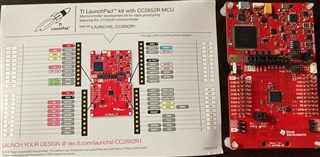
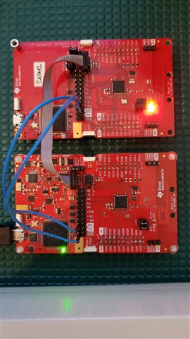
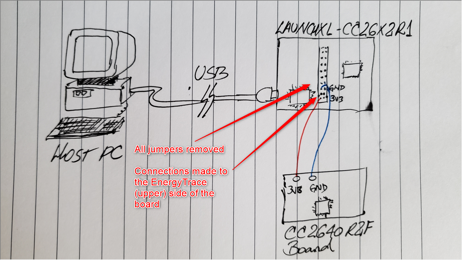
Other Parts Discussed in Thread: SYSCONFIG, , ENERGYTRACE, CC2640, CC2652R, CC2642R, LAUNCHXL-CC26X2R1, LAUNCHXL-CC2640R2, TMDSEMU110-U
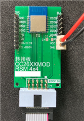
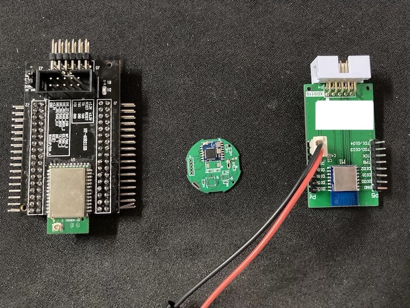
I buy a new module from another vendor, now it can run and adv.
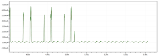
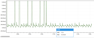
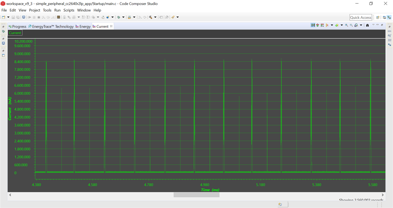
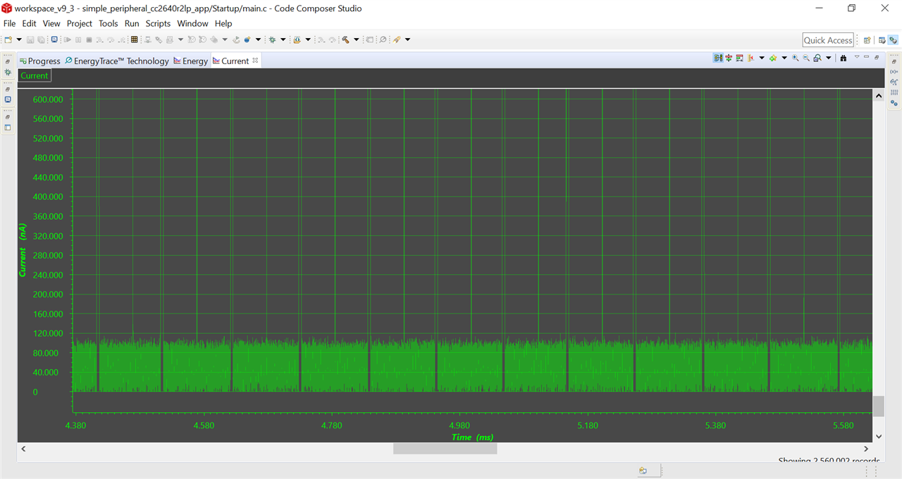
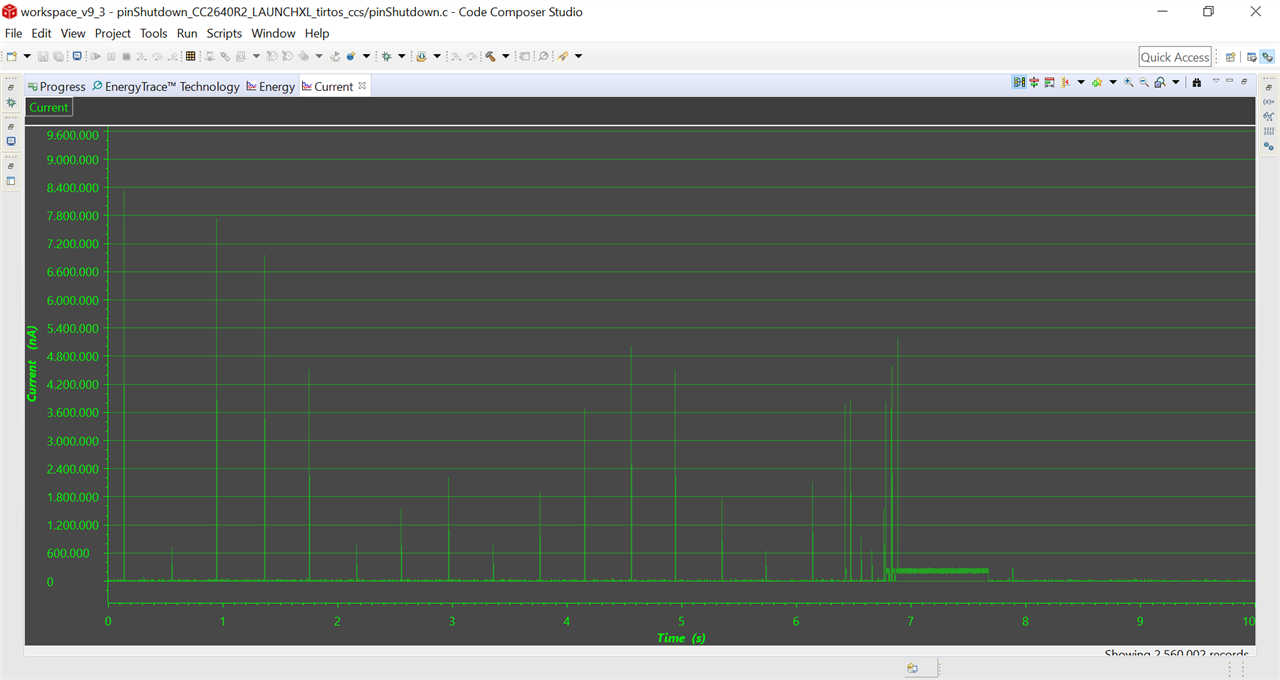
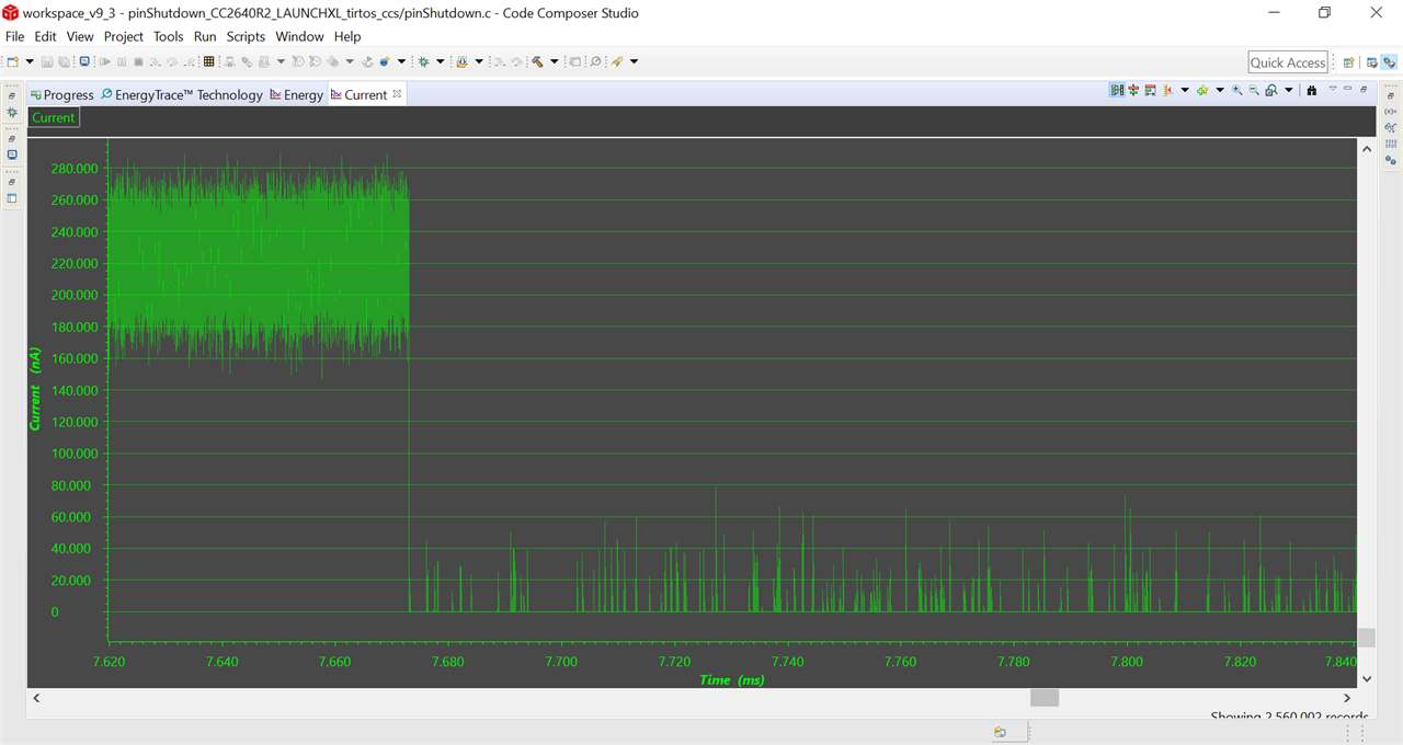
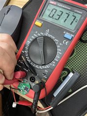
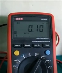
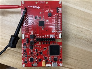
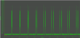
I put LOW_POWER in project config, it still have 0.7A. it is only a module, wihtout any other things.
have tried make all pin init with INPUT and NO PULL, no help.
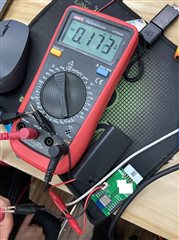
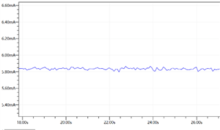
if I comment out the adv part, then current goes down.
how can I make it run in LOW_POWER?