This thread has been locked.

If you have a related question, please click the "Ask a related question" button in the top right corner. The newly created question will be automatically linked to this question.

CC2640: Minimizing sleep current when using I2C and UART

Part Number: CC2640
Other Parts Discussed in Thread: , CC2650, BLE-STACK, SYSBIOS

I have used the CC2640F128 for years now in our product and have been able to achieve about <30 microamp sleep current.

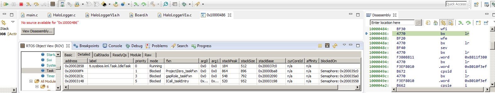
Recently I have successfully added both I2C and UART interfaces to my CC2640F128 using my ProjectZero based code.

However, I can no longer achieve sleep <30 microamp sleep currents.  My sleep currents are now a couple milliamps which is unacceptable.

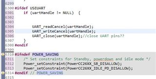
Before I attempt to go to Sleep, I call UART_close(uartHandle) and I2C_close(I2Chandle) if the handles are not NULL.

Do I need to further 'close' or 'change the state' of the 4 UART and I2C pins after I call those two functions?

If so, how do I do that?

Otherwise, I do not see what else has changed in my code that should affect Sleep current, any other suggestions on where else to look?

Thanks,

Dale

  • Hi Dale,

    Have you monitored the current consumption after initializing the pins but before opening the communication peripherals?  Using GPIOs as input pullup pins will each consume hundreds of µA as seen in the datasheet.  Are you sure that the device is still sleeping instead of being held in idle or active modes?  You could try setting up either UART or I2C to determine whether one contributes more to the power consumption than the other.

    Regards,
    Ryan

  • Hi Ryan,

    I will investigate all your suggestions in due course.

    BUT, first my four UART and I2C data pins do have 2.2k external pullups which makes them consume much more power while awake than the internal pullups would (we are plugged into AC when we are awake :) )  I just assumed upon UART_close() and I2C_close() that the data pins would have been left in a high impedance state automatically.  If they are not left in a high impedance state, how do I change them to that after UART_close() and I2C_close() are called?

    I have tried setting the data pins to the same state that my LED drive pins are left at during <30 ua sleep current which is like this:

    PIN_Config redPinTable[] = {
        Board_REDPIN | PIN_GPIO_OUTPUT_EN | PIN_GPIO_LOW | PIN_PUSHPULL | PIN_DRVSTR_MAX,
        PIN_TERMINATE
    };

    but the only way I know how to do that was to define PIN_Handle, PIN_State and PIN_Config tables for all 4 pins which eats up 96 bytes of SRAM and which also takes me over my SRAM limit and therefore I can not test my theory.

    Is there a way to change the state of the 4 data pins after UART_close() and I2C_close() which does not use SRAM?

    Thanks,

    Dale

    EDIT: Also, where do I find descriptions about what available PIN_Config table options there are and what they mean?  (like  PIN_GPIO_OUTPUT_EN, PIN_GPIO_LOW, PIN_PUSHPULL , PIN_DRVSTR_MAX etc.)

  • Would it be possible to combine all pins into a single table/handle or only configure a few of the necessary pins for testing purposes?  This should be possible since you would be configuring all of them the same direction and not using callbacks given it's a temporary usage while the communication peripherals are closed.  Pin definitions are determined inside the source/ti/drivers/PIN.h file.

    Regards,
    Ryan

  • Hi Ryan,

    I have been down quite a few rabbit holes with your suggestions but I am still a bit confused.

    I am using a 10ohm current sense resistor and reading mv to one decimal which gives me a 10 ua current resolution of power consumption for my 2640.

    You suggested that I determine if the 2640 is being held in idle or an active mode and therefore not really going to sleep, but how do I do that? 

    More Info:

    During sleep I keep the rtc timer running and I have an input pin (Board_WAKEBTN on IOID_14) that drives an interrupt so I can wake up by applying voltage to that pin.

    When I was achieving <30ua sleep current, I could wakeup the 2640 by applying less than 2v to IOID_14.  Now, with no external devices attached to the UART or I2C (and with all pullups removed), when I think it should be asleep there is still about 1ma sleep current and it takes >3v (instead of <2v) on the wakeup pin to come alive again.

    I do have a full pin config table named BoardGpioInitTable and it is called as an argument of a PIN_init(BoardGpioInitTable) which is called in the beginning of main.c, well before the BIOS_start() call.

    I have tried many ways in that BoardGpioInitTable to efficiently deal with my external pullup currents for UART and I2C.

    Knowing that this initial PIN_init() call should determine the state of the UART and I2C pins after I2C_close() and UART_close() are called, I still have not come up with a good pin configuration to reduce the pullup current to an acceptable level, perhaps I will have to reed relay these pins open during sleep if I want <30ua sleep current :(

    To convince myself that there is more to my problem that just pullup currents, I removed all devices connected to the UART or I2C pins and removed all my data line pullups yet still end up at about 1ma when I think it should be sleeping as described above.

    I have also set the configuration of the UART and I2C pins in my above described default pin config table as output pins just as I had other pins defined during my <30ua sleep configuration of many years.

    Here is that pin config table:

    const PIN_Config BoardGpioInitTable[] = {  //for explanation of parameters see PIN.h file in drivers
       //these defines are from HaloLoggerV1a.h
       //    #define Board_TPIN                  IOID_0
       //    #define Board_RHPIN                 IOID_1
       //    #define Board_V33PIN                IOID_2
    
      //    #define Board_I2C0_SCL0             IOID_3
      //    #define Board_I2C0_SDA0             IOID_4
    
       //    #define Board_UART_TX               IOID_5
       //    #define Board_UART_RX               IOID_13
    
      //    #define Board_SPI_FLASH_CS          IOID_7
      //    #define Board_SPI0_MISO             IOID_8
      //    #define Board_SPI0_MOSI             IOID_9
      //    #define Board_SPI0_CLK              IOID_10
    
       //    #define Board_REDPIN                IOID_11
       //    #define Board_GLED                  IOID_12
       //    #define Board_WAKEBTN               IOID_14
    
        Board_TPIN   | PIN_GPIO_OUTPUT_EN | PIN_GPIO_LOW | PIN_PUSHPULL | PIN_DRVSTR_MAX,      // initially off
        Board_RHPIN   | PIN_GPIO_OUTPUT_EN | PIN_GPIO_LOW | PIN_PUSHPULL | PIN_DRVSTR_MAX,      // initially off
        Board_V33PIN   | PIN_GPIO_OUTPUT_EN | PIN_GPIO_LOW | PIN_PUSHPULL | PIN_DRVSTR_MAX,      // initially off
    
        Board_I2C0_SCL0 | PIN_GPIO_OUTPUT_EN | PIN_GPIO_LOW | PIN_PUSHPULL | PIN_DRVSTR_MAX,
        Board_I2C0_SDA0 | PIN_GPIO_OUTPUT_EN | PIN_GPIO_LOW | PIN_PUSHPULL | PIN_DRVSTR_MAX,
        Board_UART_RX | PIN_GPIO_OUTPUT_EN | PIN_GPIO_LOW | PIN_PUSHPULL | PIN_DRVSTR_MAX,
        Board_UART_RX | PIN_GPIO_OUTPUT_EN | PIN_GPIO_LOW | PIN_PUSHPULL | PIN_DRVSTR_MAX,
    
        Board_SPI_FLASH_CS | PIN_GPIO_OUTPUT_EN | PIN_GPIO_HIGH | PIN_PUSHPULL | PIN_DRVSTR_MIN,  /* External flash chip select    */
        Board_SPI0_MOSI | PIN_INPUT_EN | PIN_PULLDOWN,                                            /* SPI master out - slave in */
        Board_SPI0_MISO | PIN_INPUT_EN | PIN_PULLDOWN,                                            /* SPI master in - slave out */
        Board_SPI0_CLK | PIN_INPUT_EN | PIN_PULLDOWN,                                             /* SPI clock */
    
        Board_REDPIN   | PIN_GPIO_OUTPUT_EN | PIN_GPIO_LOW | PIN_PUSHPULL | PIN_DRVSTR_MAX,      // initially off
        Board_GLED   | PIN_GPIO_OUTPUT_EN | PIN_GPIO_LOW | PIN_PUSHPULL | PIN_DRVSTR_MAX,         /* LED initially off             */
        Board_WAKEBTN   | PIN_INPUT_EN | PIN_PULLUP | PIN_IRQ_BOTHEDGES | PIN_HYSTERESIS,            /* Button is active low          */
                                                       //Board_WAKEBTN gets further mapped to Board_HasVoltsOnWakeInput in board.h....
        PIN_TERMINATE
    };

    Have I missed investigating any other of your suggestions and/or do you have any further ideas where to go from here?

    Thanks,

    Dale

  • You suggested that I determine if the 2640 is being held in idle or an active mode and therefore not really going to sleep, but how do I do that

    This can be accomplished with your IDE debugger, either by pausing the MCU state to determine if code is running or by evaluating with the ROV.

    There are some questions which have not yet been addressed:

    1. Have you monitored the current consumption after initializing the pins but before opening/using the communication peripherals? Or try to measure current after initializing UART/I2C but have not opened or used them yet?
    2. Have you enabled only UART or I2C to determine if one specific communication peripheral is directly contributing more to the issue?
    3. Which version of BLE-STACK-2 is being used and would you consider upgrading to the latest (if not already there) to determine whether this fixes the problem?

    Regards,
    Ryan

  • Hi Ryan,

    I have just now had time to continue with my <30ua sleep current quest.

    I did not realize that the IDE debugger was able to operate during sleep state.  In IDE debugging sleep state I would then expect that the voltage would be expected to rise across my 10 ohm current sensing resistor due to JTAG debug pins still in use during sleep. In fact, when I try to enter sleep (close all pins which I use, turn off all cycle clocks, terminate BLE connections and stop BLE advertising) during a debugging session, the current, when I believe we should be sleeping, rises from 1.17ma to 3.44ma.

    I am able to pause and resume the code during this 3.44ma state, but the code only pauses/breaks at assembly code as shown here (which I can single step through with the F5 key)

    Also, in that image we can see ROV reports that the IdleTask is running, does this mean that the processor is not really sleeping?

    I will now begin trying to answer your question 1-3 of your last post.

    Thanks,

    Dale

  • Thank you for providing the ROV report, at this point I believe you have confirmed that the Idle Task is running instead of entering standby.  This is most likely due to a power dependency constraint which is set in UART_open but not released during UART_close (likewise for I2C).  You can add the UART/I2C TI Driver files directly into your project to further debug their behavior, and consult the Power TI Driver to effectively enable a return to the standby state.

    Regards,
    Ryan

  • I will copy both UART and I2C driver files into my workspace as local copies and attempt to figure out how to release the pins after using UART_close() and I2C_close().

    However, why wouldn't the UART and I2C pins revert to the state of my BoardGpioInitTable, as they are supposed to, even if  UART_close() and I2C_close() did not leave their IO pins as they found them, or did they simply not close them?

    Also, I am 'unfamiliar with' and I can not find 'the Power TI Driver' that you suggest I use in order to be able to understand how I can clean up after UART and I2C are closed.  Where can 'the Power TI Driver' be found since my weak Google attempts failed?

    Thanks,

    Dale

  • If you read through Section 6 of the BLE Software Developer's Guide then it shows where to find and incorporate the TI Drivers, for example C:\ti\tirtos_cc13xx_cc26xx_2_21_01_08\products\tidrivers_cc13xx_cc26xx_2_21_01_01\packages\ti\drivers.  This is also where you will find the Power TI Driver which is further discussed in the Power Management User's Guide.  Pins should be deallocated when the driver is closed, which can also be further explored when debugging the functions.

    Regards,
    Ryan

    • Have you monitored the current consumption after initializing the pins but before opening/using the communication peripherals? Or try to measure current after initializing UART/I2C but have not opened or used them yet?
    • Have you enabled only UART or I2C to determine if one specific communication peripheral is directly contributing more to the issue?
    • Which version of BLE-STACK-2 is being used and would you consider upgrading to the latest (if not already there) to determine whether this fixes the problem?

    Above is a quote from you but the numbers 1, 2 and 3 have been automatically replaced by 'bullets' in the quote frame.  I will have to refer to your questions  as Bullet 1, Bullet 2 and Bullet 3.

    RE: Bullet 2

    Before I disabled UART as I will describe below, I discovered that perhaps it would be wise to run UART_readCancel() and UART_writeCancel() before UART_close().  After doing this the sleep current went from 1.17ma to 1.11ma (I saw this as some progress :) )

    Then, I isolated all my code that referenced UART.h functions using #ifdef USEUART .... #endif statements.  Then, I complied and ran my current code with USEUART not defined, which effectively removed UART usage from my code.  Then when I expect the CC2640 to be sleeping, the current is now 0.54ma instead of 1.11ma.

    So this seems to indicate that perhaps both UART and I2C drivers are contributing equally to my sleep current issue.

    RE: Bullet 1

    To do these suggestions required me to put a break in the code during a debugging session. 

    The only way I can load the code and start a debugging session is to have external power connected to my pcb.  This is either from a 12vdc wall wart adapter or 5vdc from  USB plug, both of which start a voltage regulator that provides charging voltage to my 2 cell NiMH battery and each of which provides the charging current through my 10 ohm current sense resistor.  Also when any external power is applied, a voltage divider resistor network provides about 2v on my IOID_14 wakeup pin so that when we wake up from sleep by interrupt on IOID_14, all my pins are re-opened, cycle_clocks started, BLE advertising starts and UART/I2C lines are opened. We do our goto sleep functions when the external voltage is removed from the pcb.

    Therefore when I hit my breakpoints to answer your questions of Bullet 1, I must also remove the external power that was powering the pcb in order to load the code in order for the voltage across my 10 ohm current sensing resistor to have any meaning for the purposes of your questions (other wise the current varies greatly based solely on the state of charge of the battery (from a couple ma to 50ma or more).

    If you understand that mouthful, then here are the breakpoints and voltages across the 10 ohm resistor during the break.

    For current consumption after initializing the pins we have Breakpoint 1 (at line 20 below)  in main.c and have 0.0324v across resistor or 3.24ma (this is the 1st breakpoint allowed (after Line 6 in below) due to high level of optimization (4-whole program, relaxed floating point and 2 for speed vs size) for my large code project):

    int main(){
      /* Register Application callback to trap asserts raised in the Stack */
    
      RegisterAssertCback(AssertHandler);
    
      PIN_init(BoardGpioInitTable); 
    
    #ifndef POWER_SAVING
      /* Set constraints for Standby, powerdown and idle mode */
      Power_setConstraint(PowerCC26XX_SB_DISALLOW);
      Power_setConstraint(PowerCC26XX_IDLE_PD_DISALLOW);
    #endif // POWER_SAVING
    
      SPI_init(); //dale
    
      /* Initialize ICall module */
      ICall_init();
    
      /* Start tasks of external images - Priority 5 */
      ICall_createRemoteTasks();
    
      /* Kick off profile - Priority 3 */
      GAPRole_createTask();
    
      ProjectZero_createTask();
    
      /* enable interrupts and start SYS/BIOS */
      BIOS_start();
    
      return 0;
    }

    For current after initializing UART/I2C but have not opened or used them yet we have Breakpoint 2 (at line 6 in blow) in my UARTcloseopen function() and have 0.0388v across resistor or 3.88ma.  NOTE: I2C is (EDIT: Removed 'NOT' from here and added 'also') also initialized at this point.

        #ifdef USEUART //20001-5
            void UARTcloseopen(void) //nex-1 //can not be called from the main loop! ! ! !
            {
              uartParams.readMode     = UART_MODE_CALLBACK; //nex-2
              uartParams.readCallback = uartRXcallback;     //nex-2
              uartParams.writeMode= UART_MODE_BLOCKING;
              uartParams.readEcho = UART_ECHO_OFF;
              uartParams.readDataMode = UART_DATA_BINARY;
              uartParams.writeDataMode = UART_DATA_BINARY;
              uartParams.baudRate = 19200; //38400; //p2f14-29 to 19200 fix comm issues TESTING THIS
              uartParams.dataLength = UART_LEN_8;
              uartParams.parityType = UART_PAR_NONE;
              uartParams.stopBits = UART_STOP_ONE;
              if (uartHandle != NULL)  {
                  UART_close(uartHandle);
              }
              uartHandle = UART_open(Board_UART0, &uartParams);
              if (uartHandle == NULL)
              {
                  //while(1); //ToDo get rid of this hang point - just took it out for now :)
              } else {
                  UART_read(uartHandle, &uartrxByte, 1); //testuart 1 byte //this read is necessary
                                                     //to turn Rx ON for continuous reads
              }
            }
        #endif

    I do not see how knowing these currents at their breakpoints can help us with determining why my sleep current is so high.  What is your reasoning for requesting them?

    RE: Bullet 3

    I would love to be able to upgrade to the latest BLE version and even migrate to a board with more memory for my huge project (I have more that 7000 lines in the .c where I write my code) .

    Here is my current memory usage (If I use more that about 95% of SRAM, BLE communications become unreliable):

    I have spent 1000's of hours coding this and even paid a consultant thousands of dollars to migrate the code to a CC2640R2F which ultimately failed.

    An upgrade of BLE version seems to me to be perhaps a very difficult attempt at a solution for my sleep current issue which has recently appeared unless you are 100% convinced BLE version is the cause of my issue.

    Thanks,

    Dale

  • Bullet 1: We are trying to differentiate whether the issue is the PIN or UART/I2C TI Driver, then what specific communication peripheral API could be causing the problem (i.e. init, open, close, cancel, etc).

    Bullet 2: If both are contributing equally then this would imply that the Power TI Driver does not affect behavior, as it would typically be an all-or-nothing effect (i.e. device is either idle or enters standby).  You could still attempt to re-initialize the standby Power constraint settings after cancelling and closing the communication peripherals.

    Bullet 3: I'm only aware that updated SimpleLink hardware and TI Drivers could mitigate the behavior, however it should by all means be possible to fully close the I2C/UART modules and enter standby afterwards.  Try implementing all POWER_SAVING code used during initialization after the I2C and UART are cancelled and closed as these settings may have changed due to TI Driver APIs.

    Regards,
    Ryan

  • When I try to add the code you suggest, where I think you suggest it should go, the compiled code is not changed due to the #ifndef line:

    Perhaps this is a clue but when I do a CCS global 'workspace search' for POWER_SAVING (82 matches found) I get confused since I even find it in app_ble_uartlog_pem3.cfg which is located in a very old workspace structure and not in my current Project Explorer tree but I did find it in my workspace using Windows search:

    Do you understand what I do not here?

    Thanks,

    Dale

    EDIT:  Next I tried adding these includes to my HaloLogger.c code, but line 6310 to 6314 are still greyed out:

    #include <ti/drivers/Power.h>
    #include <ti/drivers/power/PowerCC26XX.h>

  • I would have expected POWER_SAVING to be enabled in your project in accordance with Section 3.7 of the BLE Software Developer's Guide.

    Regards,
    Ryan

  • I just checked and yes, POWER_SAVING is and has always been, properly in place as a pre-defined symbol but the #ifndef code in main.c is NOT greyed out.

    To me it appears that at the #ifndef location in the main.c code the predefined symbol POWER_SAVING has not yet been defined which is why the #ifndef code is not greyed out there and then it is PROPERLY greyed out in my HaloLogger.c code where I close my pins before trying to go to sleep.  Is that possible?

    The Power Management API is well outside my knowledge base right now, do I really have to become somewhat of an expert in the API just so I can clean up after the TI communication drivers for UART and I2C are closed and again have <30ua sleep current?

    Thanks,

    Dale

  • I do not believe it is possible for a pre-defined setting to only apply to some parts of a project.  And you should not have to become an expert of Power Management API to solve this issue, however it would benefit the debug process to ensure that the application and UART/I2C Drivers properly release all constraints and dependencies as well as unregister any notifications after closing.  Please note that this appears to be the case when I review the tirtos_cc13xx_cc26xx_2_21_01_08 TI Driver resources.

    Regards,
    Ryan

  • I now have <10ua sleep current with my modified code that also uses the I2C driver.

    When the processor is in an active state, I flash an led to indicate so.

    During sleep the led stops flashing.

    To wakeup from sleep, >2v is applied to IOID_14.

    I am now trying to add the UART driver to this code and maintain that sleep current.

    At this point I do not have the UART Tx and Rx pins connected to the outside world.

    I only add 1 line of code in main.c which is a UART_init(); as shown here:

    int main(){
      /* Register Application callback to trap asserts raised in the Stack */
    
      RegisterAssertCback(AssertHandler);
    
      PIN_init(BoardGpioInitTable);                                                     //ToDo likely put this back in but this is overridden in HaloLogger.c line 455+ ????????????
    
    #ifndef POWER_SAVING
      /* Set constraints for Standby, powerdown and idle mode */
      Power_setConstraint(PowerCC26XX_SB_DISALLOW);
      Power_setConstraint(PowerCC26XX_IDLE_PD_DISALLOW);
    #endif // POWER_SAVING
    
      UART_init(); //p2f16-test1
    
      SPI_init(); //dale
    
      /* Initialize ICall module */
      ICall_init();
    
      /* Start tasks of external images - Priority 5 */
      ICall_createRemoteTasks();
    
      /* Kick off profile - Priority 3 */
      GAPRole_createTask();
    
      ProjectZero_createTask();
    
      /* enable interrupts and start SYS/BIOS */
      BIOS_start();
    
      return 0;
    }

    My BoardGpioInitTable is:

    const PIN_Config BoardGpioInitTable[] = {  //for explanation of parameters see PIN.h file in drivers
       //these defines are from HaloLoggerV1a.h
       //    #define Board_TPIN                  IOID_0
       //    #define Board_RHPIN                 IOID_1
       //    #define Board_V33PIN                IOID_2
    
      //    #define Board_I2C0_SCL0             IOID_3
      //    #define Board_I2C0_SDA0             IOID_4
    
       //    #define Board_UART_TX               IOID_5
       //    #define Board_UART_RX               IOID_13
    
      //    #define Board_SPI_FLASH_CS          IOID_7
      //    #define Board_SPI0_MISO             IOID_8
      //    #define Board_SPI0_MOSI             IOID_9
      //    #define Board_SPI0_CLK              IOID_10
    
       //    #define Board_REDPIN                IOID_11
       //    #define Board_GLED                  IOID_12
       //    #define Board_WAKEBTN               IOID_14
    
        Board_TPIN   | PIN_GPIO_OUTPUT_EN | PIN_GPIO_LOW | PIN_PUSHPULL | PIN_DRVSTR_MAX,      // initially off
        Board_RHPIN   | PIN_GPIO_OUTPUT_EN | PIN_GPIO_LOW | PIN_PUSHPULL | PIN_DRVSTR_MAX,      // initially off
        Board_V33PIN   | PIN_GPIO_OUTPUT_EN | PIN_GPIO_LOW | PIN_OPENDRAIN | PIN_PULLDOWN | PIN_DRVSTR_MAX,      // initially off
    
        Board_I2C0_SCL0  | PIN_GPIO_OUTPUT_EN | PIN_GPIO_LOW | PIN_OPENDRAIN | PIN_PULLDOWN | PIN_DRVSTR_MAX,
        Board_I2C0_SDA0  | PIN_GPIO_OUTPUT_EN | PIN_GPIO_LOW | PIN_OPENDRAIN | PIN_PULLDOWN | PIN_DRVSTR_MAX,
        Board_UART_RX | PIN_INPUT_EN | PIN_PULLDOWN,                       /* UART RX via debugger back channel */ 
        Board_UART_TX | PIN_GPIO_OUTPUT_EN | PIN_GPIO_HIGH | PIN_PUSHPULL, /* UART TX via debugger back channel */ 
    
        Board_SPI_FLASH_CS | PIN_GPIO_OUTPUT_EN | PIN_GPIO_HIGH | PIN_PUSHPULL | PIN_DRVSTR_MIN,  /* External flash chip select    */
        Board_SPI0_MOSI | PIN_INPUT_EN | PIN_PULLDOWN,                                            /* SPI master out - slave in */
        Board_SPI0_MISO | PIN_INPUT_EN | PIN_PULLDOWN,                                            /* SPI master in - slave out */
        Board_SPI0_CLK | PIN_INPUT_EN | PIN_PULLDOWN,                                             /* SPI clock */
    
        Board_REDPIN   | PIN_GPIO_OUTPUT_EN | PIN_GPIO_LOW | PIN_PUSHPULL | PIN_DRVSTR_MAX,      // initially off
        Board_GLED   | PIN_GPIO_OUTPUT_EN | PIN_GPIO_LOW | PIN_PUSHPULL | PIN_DRVSTR_MAX,         /* LED initially off             */
    
        Board_WAKEBTN   | PIN_INPUT_EN | PIN_PULLUP | PIN_IRQ_BOTHEDGES | PIN_HYSTERESIS,            /* Button is active low          */
                                                       //Board_WAKEBTN gets further mapped to Board_HasVoltsOnWakeInput in board.h....
    
        PIN_TERMINATE
    };
    

    The behavior changes that result from adding this 1 line of code (UART_init();)  are confusing:

    1. Connect my 2 cell NiMh battery to the 7x7 CC2640F128 (about 2.7v)
    2. I place >2v on IOID_14 so that my led will start flashing as soon as a Debug session starts.
    3. Connect a JTAG 10pin ribbon cable to my XDS110 on my CC2650 LaunchPad
    4. I start a Debug session on my CC2640F128 through my CC2650 LaunchPad and the led flashes indicating my active state.
    5. I STOP the debug session.
    6. I remove the JTAG ribbon cable from the CC2650 LaunchPad.
    7. The led still flashes and the current from the 2.7v battery is ~3ma.
    8. I remove the >2v that I have applied to IOID_14.
    9. The led stops flashing (indicating sleep have been asked for)
    10. The intermediate sleep current from the battery is 1170ua (Even repeated apply/removal of wakeup volts still produces this intermediate 1170ua sleep current)
    11. I remove/reapply the Battery power from the CC2640 (it is unknown why this step is need to get a final sleep current).
    12. From here on in, no matter how many times I apply/remove the battery or the >2v to IOID_14, the final sleep current is 680ua when sleep is expected and the led flashes whenever it is expected to. 

    When I do the above procedure without the UART_init() line, the final sleep current is <10ua.

    It would seem to me that I need an  'un-initialize' UART command that I can call after I call UART_init() so that I can maintain my <10ua sleep current.

    Here is the UART_init() driver code:

    void UART_init(void)
    {
        if (UART_count == -1) {
            /* Call each driver's init function */
            for (UART_count = 0; UART_config[UART_count].fxnTablePtr != NULL; UART_count++) {
                UART_config[UART_count].fxnTablePtr->initFxn((UART_Handle)&(UART_config[UART_count]));
            }
        }
    }

    There is so little visible in that function that I have no idea how to 'un-initialize' the UART driver.

    Where can I go from here?

    Thanks,

    Dale

  • I was still able to view your original response in my inbox :) was BoardGpioInitTable modified before or after your measurements?  My only comment at the moment is that UART_init maps to UARTCC26XX_init from the UART function table, which is detailed in the UARTCC26XX.c file.  

    void UARTCC26XX_init(UART_Handle handle)
    {
        UARTCC26XX_Object           *object;
    
        /* Get the pointer to the object */
        object = handle->object;
        object->opened = false;
    
        /* Init the power constraint flag. */
        uartRxPowerConstraint = false;
        uartTxPowerConstraint = false;
    }

    All of these resources are located in <ti_rtos_directory>products\tidrivers_cc13xx_cc26xx_*\packages\ti\drivers\ if you want to place them directly into your project for step debugging.  That being said, there is nothing in these functions which imply the power consumption increase you've observed.

    Regards,
    Ryan

  • As always, when I make a long detailed post that crystallizes my journey, I was able to fixate on all the details and I end up going deeper down a hole with another fixation.

    After I posted that long post, I just had to double check all of it and 'lo and behold' I started fixating on the fact that I said the UART pins are not connected to the outside world.  While that may be literally true, but I did have an external pullup on the UART Tx which was connected to the same floating juncture as my pullups on the two I2C pins.  This juncture gets 2.7v applied to it when I enable a 2.7v REG710NA-2.7/250 voltage regulator to my I2C ribbon cable (which sends 2.7v power to my I2C devices and 2.7volts to all my comm pullups). 

    It looks like when UART_init() is run, that the UART Tx line starts feeding current through my Tx pullup combined with my I2C pullups and then through the internal pulldowns which I have given the I2C lines in my BoardGpioInitTable.... or something like that.  When I completely removed the TX pullup that went to the high/floating ends of the I2C pullups the final sleep current after using UART_init() does go to <10ua Slight smile

    My problem is that in real life both the UART Tx and Rx lines will have pullups on them because I have to communicate with a 5 volt UART device and I have to 'level convert' my 2.8 volt nextion UART lines to 5V lines something  like this:

    And those R14 pullups would cross feed to the I2C pins during sleep and ruin my sleep current again Disappointed

    I am not sure how I can solve that yet, but I am working on it.... (I wish I could put that long post back in now ;) )

    Dale

  • I was still able to view your original response in my inbox :) was BoardGpioInitTable modified before or after your measurements? 

    BoardGpioInitTable was the same for all of that testing.

  • Thanks for the update!

  • That being said, there is nothing in these functions which imply the power consumption increase you've observed

    I still find it interesting that my UART Tx pullup did not leak until after UART_init() was placed in the code.  This implies that UART_init() does do something that causes the pullup leakage and I am still hopefull that I can 'un-initialize' the UART before I go to sleep so I can use pullups on the logic level converter that I need to use so I can talk to a 5V device with the UART driver, I will plod on... Slight smile

    Dale

  • My only comment at the moment is that UART_init maps to UARTCC26XX_init from the UART function table, which is detailed in the UARTCC26XX.c file. 

    How does UART_init map to UARTCC26XX_init since UART_init has a void argument and UARTCC26XX_init requires a UART_Handle argument?

    Dale

  • Function table pointers, UART_FxnTable and fxnTablePtr beside UARTCC26XX_fxnTable.  It's how all UART commands lead to the specific UARTCC26XX TI Driver.

    Regards,
    Ryan

  • I can't get my brain wrapped around that right now but I have been able to obtain <10ua sleep WITH my external pullup attached to Tx as described above AND with UART_init() in my code if I edit  UARTCC26XX_init as follows:

    void UARTCC26XX_init(UART_Handle handle)
    {
        UARTCC26XX_Object           *object;
    
        /* Get the pointer to the object */
        object = handle->object;
        object->opened = false;
    
        /* Init the power constraint flag. */
        uartRxPowerConstraint = true; //dale from false to true
        uartTxPowerConstraint = true; //dale from false to true
        
        //dale , since in our case we never have or expect UART communication 
        //       during sleep, then we do not need to need to leave the Tx and
        //       Rx lines open during sleep
    }

    Now, lets see if we still get <10ua after I add my code that opens UART, communicates on UART and then closes UART before going to sleep....

    Dale

  • So close yet so far Disappointed

    I have isolated a full UART session from UART_Init() to UART_close() and placed it immediately before my "Application main loop" in my function "static void ProjectZero_taskFxn(UArg a0, UArg a1) {".  There is no other UART code compiled than the below.

    Here is that code:

      //p2f16-test4 start
      UART_init();
      UART_Params_init(&uartParams);
      uartParams.readMode     = UART_MODE_CALLBACK;
      uartParams.readCallback = uartRXcallback;
      uartParams.writeMode= UART_MODE_BLOCKING;
      uartParams.readEcho = UART_ECHO_OFF;
      uartParams.readDataMode = UART_DATA_BINARY;
      uartParams.writeDataMode = UART_DATA_BINARY;
      uartParams.baudRate = 19200;
      uartParams.dataLength = UART_LEN_8;
      uartParams.parityType = UART_PAR_NONE;
      uartParams.stopBits = UART_STOP_ONE;
    
      uartHandle = UART_open(Board_UART0, &uartParams);
    
      if (uartHandle == NULL)
      {
          while(1);
      }
    
      UART_read(uartHandle, &uartrxByte, 1); //byte, this read is necessary
                                             //to turn Rx ON for continuous reads
      char Numbercmd[32] = {0,};
      strcat(Numbercmd,(char *)"pg0.ec=99999\xFF\xFF\xFF");
    //  int32_t writeback = UART_write(uartHandle, Numbercmd, strlen(Numbercmd));
    //  if (writeback != strlen(Numbercmd)){
    //      while(1);
    //  }
    
      if (uartHandle != NULL)  {
          UART_readCancel(uartHandle);
          UART_writeCancel(uartHandle);
          UART_close(uartHandle);
      }
      //p2f16-test4 end
    
      // Application main loop
      for (;;)  {

    EDIT And here is my callback code:

            static void uartRXcallback(UART_Handle handle, void *buf, size_t count) { //nex-2
              UART_read(uartHandle, &uartrxByte, 1); //testuart 1 byte //this read is necessary
                                                 //to turn Rx ON for continuous reads
    
              // Store the event.
              events |= UART_DATA_RCVD_EVT;
              //Wake task
              Semaphore_post(sem);
            }

    When the above code is run (only a UART_read is in place), the final sleep current reaches <10ua, so far so good...

    But when I un-rem the 4 lines which do a UART_write in the above code, the final sleep current is 0.93ma Disappointed

    Any ideas why that would be since I still have my power constraints set to 'true' in "void UARTCC26XX_init(UART_Handle handle)"?

    EDIT The above is of course with my pullup installed on Tx as per above post regarding  power constraints set to 'true' in "void UARTCC26XX_init(UART_Handle handle)"

    Thanks,

    Dale

  • Hi Dale,

    Please try using UART_writeCancel immediately after writing (it should be completed since UART_BLOCKING_MODE is used) since this function will disable TX and allow standby.  Also make sure the while(1) loop is not entered which cause the device to stay in active mode.

    Regards,
    Ryan

  • My while(1) statements are not being entered, I know this since my LED does start flashing after this UART test code when the main loop is entered.  Due to my high program optimization level, I am unable to put breakpoints at the while(1) lines.  EDIT I know that if I just pause execution after I start the debug session, the code would break at the while(1) statement but  using my flashing LED method of knowing that code execution has passed through the while(1)'s doesn't make me have to remember to pause execution just to see if the while(1)'s were entered.

    As per your suggestion that I put "UART_writeCancel immediately after writing", the final sleep current is still 0.93ma.

    Here is where I added that UART_writeCance, I am unsure why moving the UART_writeCancel there would be any different from where my code placed the UART_writeCancel just before the UART_close.

      //p2f16-test4 start
      UART_init();
      UART_Params_init(&uartParams);
      uartParams.readMode     = UART_MODE_CALLBACK;
      uartParams.readCallback = uartRXcallback;
      uartParams.writeMode= UART_MODE_BLOCKING;
      uartParams.readEcho = UART_ECHO_OFF;
      uartParams.readDataMode = UART_DATA_BINARY;
      uartParams.writeDataMode = UART_DATA_BINARY;
      uartParams.baudRate = 19200;
      uartParams.dataLength = UART_LEN_8;
      uartParams.parityType = UART_PAR_NONE;
      uartParams.stopBits = UART_STOP_ONE;
    
      uartHandle = UART_open(Board_UART0, &uartParams);
    
      if (uartHandle == NULL)
      {
          while(1);
      }
    
      UART_read(uartHandle, &uartrxByte, 1); //byte, this read is necessary
                                             //to turn Rx ON for continuous reads
      char Numbercmd[32] = {0,};
      strcat(Numbercmd,(char *)"pg0.ec=99999\xFF\xFF\xFF");
      int32_t writeback = UART_write(uartHandle, Numbercmd, strlen(Numbercmd));
      UART_writeCancel(uartHandle);
      if (writeback != strlen(Numbercmd)){
          while(1);
      }
    
      if (uartHandle != NULL)  {
          UART_readCancel(uartHandle);
          UART_writeCancel(uartHandle);
          UART_close(uartHandle);
      }
      //p2f16-test4 end

    since this function will disable TX and allow standby

    Remember though that  my external pullup is now re-installed on Tx as per my above post regarding  power constraints set to 'true' in "void UARTCC26XX_init(UART_Handle handle)"

    Thanks,

    Dale

  • My apologies Dale as I had not closely observed the conditions of your existing UART_writeCancel/close.  You are correct that the additional UART_writeCancel should not have changed matters.  Does the sleep current status improve if the external pin connections are removed (as a test)?  I don't think you needed to alter the uart[Rx/Tx]PowerConstraint in UARTCC26XX_init since they are modified by threadSafeStdbyDis[Set/Release] during UART TI Driver operation.

    Regards,
    Ryan

  • If I remove my external pullup on Tx and un-rem the 4 lines which do a UART_write, the final sleep current is still 0.93ma.

    This is very confusing that the UART_write command seems to reconfigure the TX pin after a UART_init so that <10ua sleep is no longer attained...

    As per my previous post, the only way to achieve <10ua sleep with ONLY the UART_init in the code AND with my TX pullup was to set the uart[Rx/Tx]PowerConstraints to "true" in UARTCC26XX_init 

    Thanks,

    Dale

  • Is there a possibility that since my UART Tx is defined as IOID_5 and since IOID_5 is also connected to pin 4 of the 10 conductor jTag Debug ribbon cable, that there is some debugging firmware still operational in the firmware that affects the state of IOID_5 even with the jTag Ribbon cable removed?

    If this is so, is there a way to compile the firmware without that section of code to see if it is what is causing this?

    Thanks,

    Dale

  • Can you further debug UARTCC26XX.c to ensure that threadSafeStdbyDisRelease(&uartTxPowerConstraint); is called either during UARTCC26XX_write or UARTCC26XX_writeCancel?  This is required to allow standby mode again and I'm not confident that it is accomplished.  It may be worth adding to the case in UARTCC26XX_writeCancel where there is nothing to write and the TX FIFO is empty, or to UARTCC26XX_close.  You could also test callback mode to determine whether it performs any better.

        /* Return if there is nothing to write and TX FIFO is empty. */
        if ((!object->writeSize) && (!UARTBusy(hwAttrs->baseAddr))) {
            threadSafeStdbyDisRelease(&uartTxPowerConstraint); //ADDED
            Hwi_restore(key);
            return;
        }

    Which device package are you using?  This may apply to RHB but not RGZ or RSM.  You could make sure that 2-pin JTAG is selected from the target configuration (ccxml) file in CCS.

    Regards,
    Ryan

  • Which device package are you using?  This may apply to RHB but not RGZ or RSM.  You could make sure that 2-pin JTAG is selected from the target configuration (ccxml) file in CCS.

    My cc2640f128 is on an FCC certified daughterboard that solders onto my pcb.

    The cc2640f128 is under a soldered on shield on that daughterboard but I know it is a 7x7 configuration.

    Here is my debugging target info:

  • 7x7 is RHB and the target configuration is set for 2-pin so there should not be any internal JTAG interference.

    Regards,
    Ryan

  • Can you further debug UARTCC26XX.c to ensure that threadSafeStdbyDisRelease(&uartTxPowerConstraint); is called either during UARTCC26XX_write or UARTCC26XX_writeCancel? 

    threadSafeStdbyDisRelease was called in UARTCC26XX_writeCancel.

    It may be worth adding to the case in UARTCC26XX_writeCancel where there is nothing to write and the TX FIFO is empty, or to UARTCC26XX_close

    I have attached my modified UARTCC26XX.c with your 'ADDED' line, but still we have .93ma standby.

    UARTCC26XX.zip

    You could also test callback mode to determine whether it performs any better.

    I am not sure how to do that quickly, I will try to figure it out...

  • I don't think you needed to alter the uart[Rx/Tx]PowerConstraint in UARTCC26XX_init since they are modified by threadSafeStdbyDis[Set/Release] during UART TI Driver operation.

    After further studying the UART drivers I decided that I should come up with a solution that does not alter the uart[Rx/Tx]PowerConstraint in UARTCC26XX_init, so I set them back to 'false' and carried on.

    Then, for some unknown reason, I could only achieve <10ua sleep if UART_read() was NOT in my code but the UART_write() COULD be in the code.

    I gave up trying to figure out how that switch happened.

    On a lark though, I had a thought that since we were having trouble telling the power constraints that standby state should be allowed after my UART_close, perhaps I should never let the power constraints be set to prevent Standby state after a UART_close to begin with.

    Sooo... in both UARTCC26XX_read() and UARTCC26XX_write() (in UARTCC26XX.c), I REMMED out the lines:

        /* Set constraint for sleep to guarantee transaction */
    //    threadSafeStdbyDisSet(&uartRxPowerConstraint);   //dale try remmed out - WOW it worked!! <10ua final sleep

    And holy "you know what" it worked!!!!

    I now have all my previously written UART code "active and running" back inside my code and I can attain <10ua final sleep (standby) current Slight smile

    Right now, this seems to be the final resolution to my topic issue, but there were other things discovered along the way.

    I will mark this as resolved for now but it might be worthwhile leaving the topic open for a while since I am not totally comfortable yet with this solution.

    There should be a better general way to turn this on/off if someone needs to worry about cutting off UART transmissions/receipts when they enter standby, but fortunately I don't care about that. 

    I hope this solution will continue to accomplish what I need it to.....

    Thanks for all the help Ryan,

    Dale

  • Well, some things are just too good to be true :(

    I am now testing this solution by sending and receiving UART data to/from an actual external device using my 2.8v to 5v level shifters on UART Tx and Rx.

    Unfortunately, UART reads no longer get triggered and sent to my uartRXcallback function when there is valid data at the Rx pin.

    To make my code work again, I only have to UNREM the lines, in both UARTCC26XX_read() and UARTCC26XX_write() (in UARTCC26XX.c):

    /* Set constraint for sleep to guarantee transaction */
    threadSafeStdbyDisSet(&uartRxPowerConstraint); //dale has to be IN to trigger UART reads

    BUT, when I do that I can no longer attain <10us final sleep.

    I am considering putting those two lines in an 'if' statement that does NOT call threadSafeStdbyDisSet() if a global variable named 'dontCall' is true.

    Then, when I close pins and set up to go to sleep I set dontCall = 1 and then do both a write and then a read so I can get my <10ua final sleep current back.

    Of course as soon as I wake up from sleep I would have to set dontCall back to 0.

    This is kludgy and messy, can you think of another way to do this?

    Thanks,
    Dale

  • Thanks for the update.  That is quite a convoluted solution, however I don't have any recommendations at the moment.  If it works to address the problem, then I recommend you continue using it.

    Regards,
    Ryan

  • After a crazy day of coding the convoluted solution which I proposed and also many more ideas, I still did not have a working solution.

    BUT, I did have a lot more knowledge about the UART driver files and the TI-RTOS Power Manager for CC26xx.

    It eventually seemed that only my continuous UART_reading using callback mode was causing the issue.

    Despite calling UART_readCancel() before UART_close(), the power constraints were never left in a state that <10ua final sleep could be reached.

    So I went backwards and started with completely stock UART driver files (UART.h, UART.c, UARTCC26XX.h and UARTCC26XX.c) and then added at the end of the UARTCC26XX_close() function, this single line of code (in the file UARTCC26XX.c) :

    threadSafeStdbyDisRelease(&uartRxPowerConstraint);

    And that is it.....

    I am now sending and receiving UART data to/from an actual external device using my 2.8v to 5v level shifters on UART Tx and Rx and I can still get <10ua final sleep current Slight smile

    The worst part of this solution is that it now sorta makes sense to me if somehow the matching pairs of Power_setConstraint() and Power_releaseConstraint() were somehow getting out of sync...

  • The story continues....

    When I wake up from this 'standby/sleep' state of <10ua, my AON_RTC.sec register has been reset to 0 and all my RAM variables have re-initialized values like we started from a 'hard reboot' state where main.c routines begin again.

    I wake up by applying voltage to pin IOID_14 which has interrupt code that opens pins and I2C and UART and BLE advertising again.

    During this sleep state I can step through a Debug session and see that the AON_RTC.sec register is incrementing properly (in the registers tab) and my  RAM variable values are good (as seen in the expressions tab) .  So, the AON_RTC.sec register must be being reset somehow when I wake up along with the RAM variable values re-initialized.

    I am not able to continue the debug session after I apply voltage to IOID_14 since debug session crashes with an error:

    "JTAG Communication Error: (Error -1170 @ 0x0) Unable to access the DAP"

    Any ideas what to look at next here?

    Thanks,

    Dale

  • How do you initialize/configure the IOID_14 pin?  Your description is similar to that of a device entering and exiting shutdown mode (ie. AON domain and RAM being reset, JTAG disconnect).  Can you determine whether your device is re-starting at main without use of the debugger?

    Regards,
    Ryan

  • Can you determine whether your device is re-starting at main without use of the debugger?

    I put code in main.c that flashes a yellow LED for 2 seconds each time the main.c code is run.  Since the yellow LED flashes I can say that yes the main.c code is running every time I re-apply high voltage to IOID_14 without a debug session running. 

    How do you initialize/configure the IOID_14 pin?

    I started with the existing code that de-bounces a button press in ProjectZero and then modified it slightly.

    I define functions and set the pins parameters using a pin table like this:

        static void user_enqueueRawAppMsg(app_msg_types_t appMsgType, uint8_t *pData, uint16_t len );
        static void buttonCallbackFxn(PIN_Handle handle, PIN_Id pinId);
        static void buttonDebounceSwiFxn(UArg buttonId);
        static void user_handleButtonPress(button_state_t *pState);
        
        PIN_Config buttonPinTable[] = {
            Board_HasVoltsOnWakeInput | PIN_INPUT_EN  | PIN_IRQ_POSEDGE,                                                              // Board_WAKEBTN   | PIN_INPUT_EN | PIN_PULLUP | PIN_IRQ_BOTHEDGES | PIN_HYSTERESIS,
            PIN_TERMINATE
        };

    Then this in ProjectZero_init(): 

      // Setup callback for button pin
      if (PIN_registerIntCb(buttonPinHandle, &buttonCallbackFxn) != 0) {
        Log_error0("Error registering button callback function");
        Task_exit();
      }
    
      // Create the debounce clock objects for Button
      Clock_Params clockParams;
      Clock_Params_init(&clockParams);
    
      clockParams.arg = Board_HasVoltsOnWakeInput;
      Clock_construct(&buttonWakeDebounceClock, buttonDebounceSwiFxn,
                      1000 * (1000/Clock_tickPeriod),
                      &clockParams); //~1 second total debounce

    Here is the function codes:

    static void user_enqueueRawAppMsg(app_msg_types_t appMsgType, uint8_t *pData,
                                      uint16_t len)
    {
      // Allocate memory for the message.
      app_msg_t *pMsg = ICall_malloc( sizeof(app_msg_t) + len );
    
      if (pMsg != NULL)
      {
        pMsg->type = appMsgType;
    
        // Copy data into message
        memcpy(pMsg->pdu, pData, len);
    
        // Enqueue the message using pointer to queue node element.
        Queue_enqueue(hApplicationMsgQ, &pMsg->_elem);
        // Let application know there's a message.
        Semaphore_post(sem);
      }
    }

    static void buttonCallbackFxn(PIN_Handle handle, PIN_Id pinId)
    {
      PIN_setConfig(handle, PIN_BM_IRQ, pinId | PIN_IRQ_DIS);
      // Start debounce timer
      switch (pinId)
      {
        case Board_HasVoltsOnWakeInput:
          Clock_start(Clock_handle(&buttonWakeDebounceClock));
          break;
      }
    }

    static void buttonDebounceSwiFxn(UArg buttonId)
    {
      // Used to send message to app
      button_state_t buttonMsg = { .pinId = buttonId };
      uint8_t        sendMsg   = FALSE;
    
      // Get current value of the button pin after the clock timeout
      uint8_t buttonPinVal = PIN_getInputValue(buttonId);
    
      // Set interrupt direction to opposite of debounced state
      if (buttonPinVal)
      {
        // Enable negative edge interrupts to wait for removal of volts 
        PIN_setConfig(buttonPinHandle, PIN_BM_IRQ, buttonId | PIN_IRQ_NEGEDGE);
      }
      else
      {
        // Enable positive edge interrupts to wait for an apply volts 
        PIN_setConfig(buttonPinHandle, PIN_BM_IRQ, buttonId | PIN_IRQ_POSEDGE);
      }
    
      switch(buttonId)
      {
        case Board_HasVoltsOnWakeInput:
          if (buttonPinVal && buttonWAKEstate)
          {
            // we DO have volts
            buttonMsg.state = buttonWAKEstate = 1;
            sendMsg = TRUE;
          }
          else if (!buttonPinVal && !buttonWAKEstate)
          {
            // we DON'T have volts
            buttonMsg.state = buttonWAKEstate = 0;
            sendMsg = TRUE;
          }
          break;
      }
    
      if (sendMsg == TRUE)
      {
        user_enqueueRawAppMsg(APP_MSG_BUTTON_DEBOUNCED,
                          (uint8_t *)&buttonMsg, sizeof(buttonMsg));
      }
    }

    static void user_handleButtonPress(button_state_t *pState)
    {
      switch (pState->pinId)
      {
        case Board_HasVoltsOnWakeInput:
            checkwakebutton(); //this is where we get woken up from sleep with an interrupt!!!!
            break;
      }
    }

    All of which seem to work together up to a point as I have now been setting breakpoints and stepping through the code that gets run after I apply voltage to IOID_14.

    The buttonDebounceSwiFxn() does get triggered, sendMSG does get set to TRUE and user_enqueueRawAppMsg(APP_MSG_BUTTON_DEBOUNCED,
    (uint8_t *)&buttonMsg, sizeof(buttonMsg)) gets run at the end of buttonDebounceSwiFxn().  At this point the code still is running and can be paused but a breakpoint in the user_enqueueRawAppMsg() function never gets triggered so ultimately the user_handleButtonPress() never gets called which is where my routine that really wakes things up after the interrupt is placed.

    I am not sure why I no longer get a JTAG disconnect when I break and step through the code like the above method.

    Does this give you any clues as to what is happening?

    Thanks,

    Dale

  • Your code is being reset based on the yellow LED indicator, this could be from hardware (ex. short between IOID_14 and the power or reset pins) or software (ex. assertion) but it is difficult to tell with the information available.

    Regards,
    Ryan

  • Your code is being reset based on the yellow LED indicator, this could be from hardware (ex. short between IOID_14 and the power or reset pins)

    I can share the part of the schematic that shows the IOID_14 connections and the Reset pin connections:

    The Reset pin only goes to the Jtag header and I never control that pin in code.

    The IOID_14 gets its voltage to wakeup from a voltage divider on either the 5v USB connector or a 12v header plug.

    I think this would rule out a hardware reset, wouldn't you?

    or software (ex. assertion)

    I never assert the Reset pin in code, is there some other assertion that could cause this in software?

    Thanks,

    Dale

  • What is the input voltage level at IOID_14?  Voltage higher than the VDD could cause internal hardware failure and damage to the device.  A watchdog trigger, TI-RTOS/HWI failure, or RF stack issue could all cause an assert.  You can review the main assert handler in your code to determine how the firmware handles assertations.

    Regards,
    Ryan

  • The max on an pin according to datasheet is 4.1v.  At 5v In, the divider gives about 3.7v and at 12v In, the divider gives about 2.8v.

    Sorry, I guessed wrong at what an assertion was ;)

    I found that in my cc2640.cfg I have BIOS.assertsEnabled = false;

    In main.c I have not edited the AssertHandler function:

    void AssertHandler(uint8 assertCause, uint8 assertSubcause)
    {
      // Open the display if the app has not already done so
      if ( !dispHandle )
      {
        dispHandle = Display_open(Display_Type_LCD, NULL);
      }
    
      Display_print0(dispHandle, 0, 0, ">>>STACK ASSERT");
    
      // check the assert cause
      switch (assertCause)
      {
        case HAL_ASSERT_CAUSE_OUT_OF_MEMORY:
          Display_print0(dispHandle, 0, 0, "***ERROR***");
          Display_print0(dispHandle, 2, 0, ">> OUT OF MEMORY!");
          break;
    
        case HAL_ASSERT_CAUSE_INTERNAL_ERROR:
          // check the subcause
          if (assertSubcause == HAL_ASSERT_SUBCAUSE_FW_INERNAL_ERROR)
          {
            Display_print0(dispHandle, 0, 0, "***ERROR***");
            Display_print0(dispHandle, 2, 0, ">> INTERNAL FW ERROR!");
          }
          else
          {
            Display_print0(dispHandle, 0, 0, "***ERROR***");
            Display_print0(dispHandle, 2, 0, ">> INTERNAL ERROR!");
          }
          break;
    
        case HAL_ASSERT_CAUSE_ICALL_ABORT:
          Display_print0(dispHandle, 0, 0, "***ERROR***");
          Display_print0(dispHandle, 2, 0, ">> ICALL ABORT!");
          HAL_ASSERT_SPINLOCK;
          break;
    
        default:
          Display_print0(dispHandle, 0, 0, "***ERROR***");
          Display_print0(dispHandle, 2, 0, ">> DEFAULT SPINLOCK!");
          HAL_ASSERT_SPINLOCK;
      }
    
      return;
    }

    If I put a breakpoint on the first line of that AssertHandler() function, it does not get triggered before I get a JTAG disconnect after applying 12v In (or 2.8v at IOID_14).

    Does that confirm that an Assert is not causing the issue?

    Thanks,

    Dale

  • 3.7 V could still be 0.3 V above the VDD, which is not a recommended operation for the device.  The AssertHandler action appears to be HAL_ASSERT_SPINLOCK (i.e. forever loop) instead of initiating a soft reset.

    Regards,
    Ryan

  • 3.7 V could still be 0.3 V above the VDD, which is not a recommended operation for the device.

    As I said, I am testing only with the 12v voltage divider which gives 2.8v on IOID_14.  I plan to change the voltage divider for USB wakeup to get about 3v which should be fine in the future.  By the way, I have never had an issue waking up previous versions of this board by USB with the divider that puts 3.7v on IOID_14.

    The AssertHandler action appears to be HAL_ASSERT_SPINLOCK (i.e. forever loop) instead of initiating a soft reset.

    But how could HAL_ASSERT_SPINLOCK be hit if a breakpoint on the 1st line of the AssertHandler ( "if ( !dispHandle )" ) is never triggered? (Due to high optimization, I can only put a breakpoint on the first line).

    Thanks,

    Dale

  • I have now been able to trace code execution much further after 2.8v has been applied to IOID_14 and it appears from the below images that something goes wrong with the IdleTask stack to cause my code to halt execution.

    I have never seen the IdleTask stack peak ever go above 240 out of 512 until now.

    My code has been running solidly for many months and this wakeup from <10ua sleep state seems to be causing the stack error somehow.

    Does this get us any further?

    EDIT: In order to get this far I have not been able to include code that re-opens the UART after wakeup yet.

    Thanks,

    Dale

  • There is a BLE-Stack Debugging Guide which discusses some causes of stack overflow, albeit not typically expected of the Idle Task stack.  Does this occur without any changes to the TI Drivers or BLE-Stack source code?

    If you are experiencing further issues unrelated to the original post based on UART/I2C sleep current, then it may be best to start a new thread.  

    Regards,
    Ryan

  • There is a BLE-Stack Debugging Guide which discusses some causes of stack overflow, albeit not typically expected of the Idle Task stack.

    I can't find information about debugging IdleTask stack issues in that document. Generally the solutions given for stack size errors in general is just to increase the size.

    The size of this stack is set in my cc2640.cfg by a variable called Program.stack (hence I call it the Program.stack). 

    I have tried going from 512 to 768 but then my program will not fit in memory. I am already compiling at the highest optimization level that works for me which is 'Whole Program and Size vs Speed of 2".

    I tried 640 but it compiles using 128 bytes more of SRAM than 512 did but ROV still shows it as 512.

    So, I can not see how it works with more Program.stack size 

    EDIT: So far I am unable to find out how to change the size if the IdleTask stack.

    Besides, if it is a stack size issue, why does it only show up when waking up from this sleep state?

    Does this occur without any changes to the TI Drivers or BLE-Stack source code?

    The only change to any of those was the addition of the line threadSafeStdbyDisRelease(&uartRxPowerConstraint); at the end of the UARTCC26XX_close() function (in the file UARTCC26XX.c). With this line in, I wake up from <10ua final sleep current with the IdleTask stack error.

    But, even without any changes to the TI Drivers or BLE-Stack source code, the wakeup behavior is the same IdleTask stack error but I wake up from 900ua final sleep current.

    If you are experiencing further issues unrelated to the original post based on UART/I2C sleep current, then it may be best to start a new thread.  

    At this point I am still believing that this wake up issue is somehow related to having finally attained low sleep current (even 900ua would be low considering that I started this topic with 2-3000ua sleep current ;) ).

    If you think I should start a new topic about waking up from sleep issues then I will do that.

    Thanks,

    Dale

    EDIT: I tried not starting to BLE advertise after waking up but the same IdleTask stack error occurs exactly as before.