


Part Number: CC1352P7
Other Parts Discussed in Thread: CC1352P
Hello Folks,
I have narrowed down CC1352P7 MCU for BLE Central application as this module also have integrated PA for better Range at +20dBm.
One might ask why stick to only CC1352P7 ? The reason being that's the only MCU which is available in TI.com's Inventory right now.
While going through the Reference designs available for CC1352P series MCUs I observed.
- Reference Design for LP-CC1352P7-4 Launchpad has CC1352P7 and RF circuitry which can output only +10dBm Output and that too for TX only (Ref. - Image A)
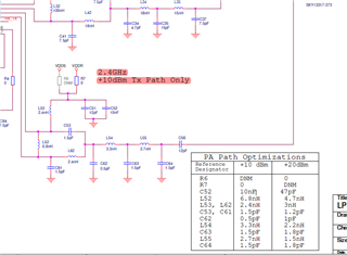
- What changes are to be done in the schematic to use CC1352P7 at +20 dBm for BLE instead of +10dBm ? The BOM changes are given for 20 dBm but the table doesn't match with the Schematic. (Image & BOM attached)
 MCU077A-LP-CC1352P7-4 -RevA_BOM.xlsx
 - Also, the Documents available for LP-CC1352P7-4 have lot of discrepancy between the Schematic and the BOM (Image attached above). The designator and values are not matching for most of the passive components.
- What changes are to be done in the schematic to use CC1352P7 at +20 dBm for BLE instead of +10dBm ? The BOM changes are given for 20 dBm but the table doesn't match with the Schematic. (Image & BOM attached)
- Reference Design for LAUNCHXL-CC1352P-2 has CC1352P1F3RGZ and RF circuitry which can output +20 dBm Output
- Can the RF Circuitry of +20 dBm output be used with CC1352P7 ?
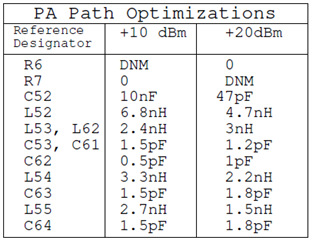
- I also compared the +20dBm circuitory in LAUNCHXL-CC1352P-2 & LP-CC1352P7-4 (PA Table) the values doesn't match for both of the schematics.
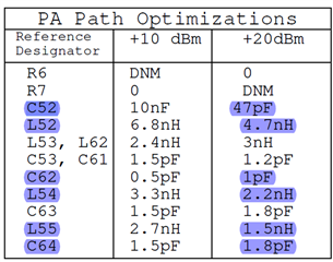
To sum it up the PA Optimization table (provided in Schematic), Schematic & BOM for the LP-CC1352P7-4 doesn't match with each other at all, which creates a confusion as which of them should be followed to achieve +20dBm output.
I request TI Team to please help me with the correct documents for LP-CC1352P7-4 so that I can proceed ahead with the design for the custom board for +20dBm, since we have product launch in December and discrepancy in documents have already wasted lot of critical time left for us.

