Hi,
My product only uses UART to connect to CC2340.
How to set up can be consistent?
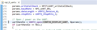
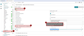
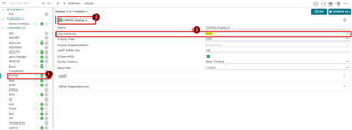
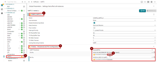
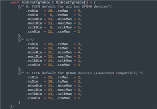
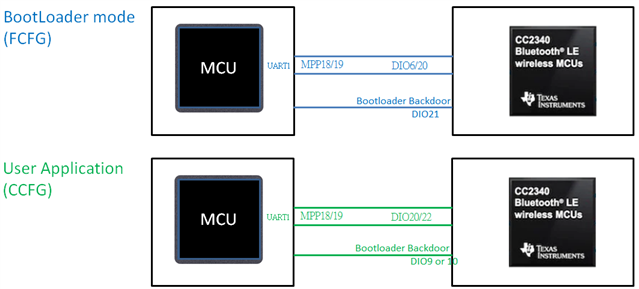
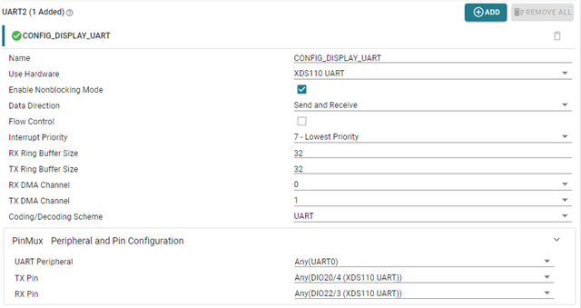
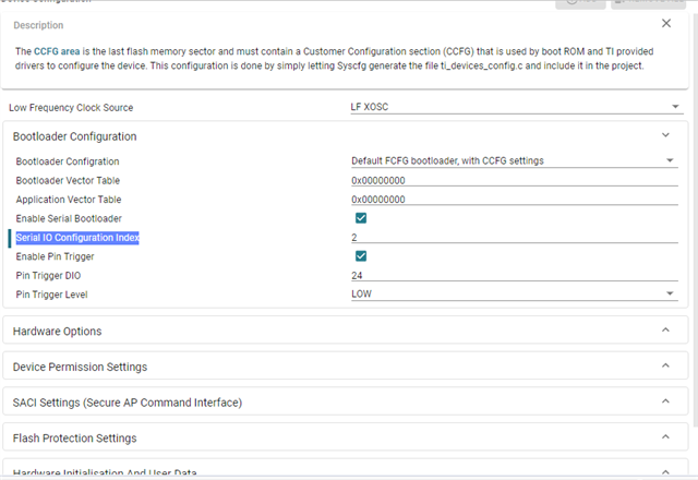
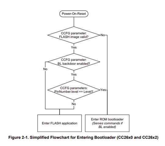
Bootloader mode: UART Dio6 and Dio20
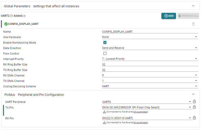
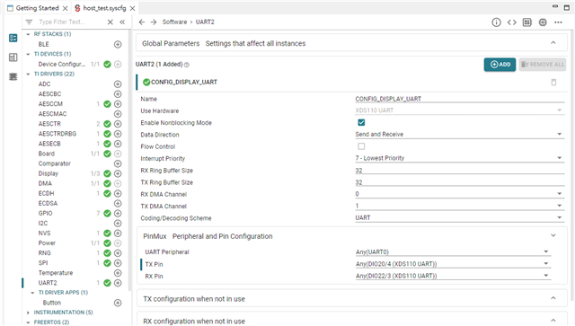
host_test application: UART Dio20 and Dio22
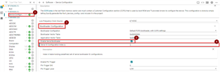
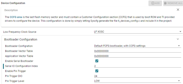
Currently the CCS setting 'Use Hardware' cannot be changed
Thanks,
Aries
Original question:

Hi,
My product only uses UART to connect to CC2340.
How to set up can be consistent?
Bootloader mode: UART Dio6 and Dio20
host_test application: UART Dio20 and Dio22
Currently the CCS setting 'Use Hardware' cannot be changed
Thanks,
Aries