This thread has been locked.

If you have a related question, please click the "Ask a related question" button in the top right corner. The newly created question will be automatically linked to this question.

CC2642R-Q1: -R vs. C load of 32k768

Part Number: CC2642R-Q1

Tool/software:

Hi There, 

In the App note, Crystal Oscillator and Crystal Selection for the CC13xx, CC26xx, and CC23xx Family of Wireless MCUs (Rev. L)

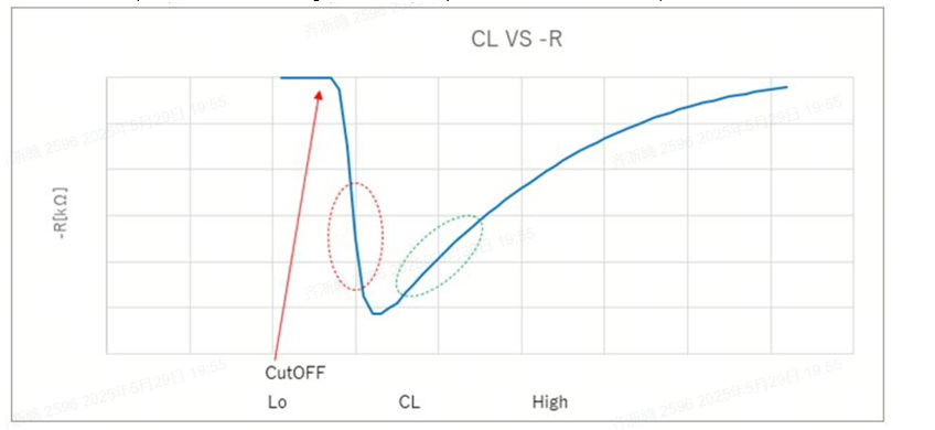
the -R vs. C load is Inverse-square, shows in equation (7). 

But customer asked crystal vendor, they shows below curve. maybe the equation 7 meet part of the curve by ignore some other coefficient. 

could you please share more than the equation's curve? what's the TI's cutoff number?

BR. Albin

  • The information shared by the crystal supplier -R vs C load is shown in the figure above, and it is also mentioned that the negative feedback amplifier circuit will have a cutoff region and an amplification region. Add a question: What are the values of C load corresponding to the cut-off area and amplification area of the CC2642 negative feedback amplifier circuit?

  • Hello,

    I've assigned this to an expert, and they should get back to you tomorrow.

    Best,

    Nima Behmanesh

  • Hi Guoqing,

    We do not have the value for the cutoff point for the amplifier. As long as you are using a crystal that within the datasheet, you should not reach that point. To help you as best as I can, could provide more details on the background for this question?

    Regards,

    HG

  • Background: When the C load of 32.768K crystal matches 12PF, all PCBA can start to vibrate . When the C load of 32.768K crystal matches 8PF, the 32.768K of some PCBA cannot start vibration. Why can't the 32.768K of some PCBA start vibration when C load matches 8PF?What is the root cause?

  • Hi Guoqing,

    The datasheet states minimum load capacitance of 6 pF. This is refers to the total load capacitance including the parasitics. It might be that the total load capacitance on your board is less than 6 pF. The total capacitance is given as (C1 x xC2)/(C1 + C2) + Cparasitic, where C1 and C2 are the two crystal load capacitors. 

    Why are you trying to test with different load capacitors? You should use a load capacitance that gives the least offset. Please see section 6.3 of CC13xx/CC26xx Hardware Configuration and PCB Design Considerations for how to tune the 32kHz crystal.

    Could you also share the crystal that you are using? What load capacitance is that crystal expecting?

    Regards,

    HG

  • We encountered three problems.

    1、During the PV experiment, there were 4 cases where CC2642 reported a CLK loss fault. It was observed that one 48M crystal stopped oscillating. Attached is the FA analysis report from the crystal manufacturer. SEAM3225 48M10PF-A120不良分析报告25.4.22.xls

    2、A sample, the matching capacitor for the 32.768K crystal oscillator is 8.2 pf.    C sample , 8.2pf  capacitor  does not enable the 32.768K oscillator to start,  When using 12pf, the crystal can start oscillating.  Attached is the  crystal datasheet and Match report TROQ-ARNE32768023-2X.pdfTXC-AH03200011.pdfMatch report-AH03200011-A202501158.pdf

    3、What is the value of the parasitic capacitance between the CC2642 pin and the PCB? 

  • The previous reply was not complete. Please refer to this one.

    1、During the PV experiment, there were 4 cases where CC2642 reported a CLK loss fault. It was observed that one 48M crystal stopped oscillating. Attached is the FA analysis report from the crystal manufacturer. SEAM3225 48M10PF-A120不良分析报告25.4.22.xls  均联智行线路板测试报告_TROQ - 25.1.10.pdfARL48000357-2X.pdfARNE32768023-2X.pdf

    2、A sample, the matching capacitor for the 32.768K crystal oscillator is 8.2 pf.    C sample , 8.2pf  capacitor  does not enable the 32.768K oscillator to start,  When using 12pf, the crystal can start oscillating.  Attached is the  crystal datasheet and Match report 0741.Match report-AH03200011-A202501158.pdf3465.TXC-AH03200011.pdf

    3、What is the  estimated  value of the parasitic capacitance between the CC2642 pin and the PCB?  

    4、If HCI_EXT_SetSCACmd(500) , setting the sleep clock tolerance to 40 ppm, will the significant frequency deviation during high-temperature conditions cause CLK loss?

  • Hi Zhegan,

    The parasitic capacitance of the crystal traces is dependent on the design. By making the traces longer, the parasitic capacitance will increase. Have you tried to route out the LF clock to a GPIO and measure what the frequency is? Can you output the LF clock and measure the frequency with a frequency counter? Then, increase and decrease the load capacitance until you get exactly or very close to 32.768 kHz? If you do this, you can find out the total load capacitance and the stray capacitance.

    Using HCI_EXT_SetSCACmd(500) will not affect the CLK loss. Clock loss occurs only when the IC cannot detect a clock signal.

    Regards,

    HG

  • If the  load capacitance matched with the 32K crystal is too small, which parameters of the crystal will be affected, and what adverse consequences will it cause?

    If the load capacitance matched with the 32K crystal is too small, will the chip report clock loss error?