This thread has been locked.
If you have a related question, please click the "Ask a related question" button in the top right corner. The newly created question will be automatically linked to this question.
Hi ,
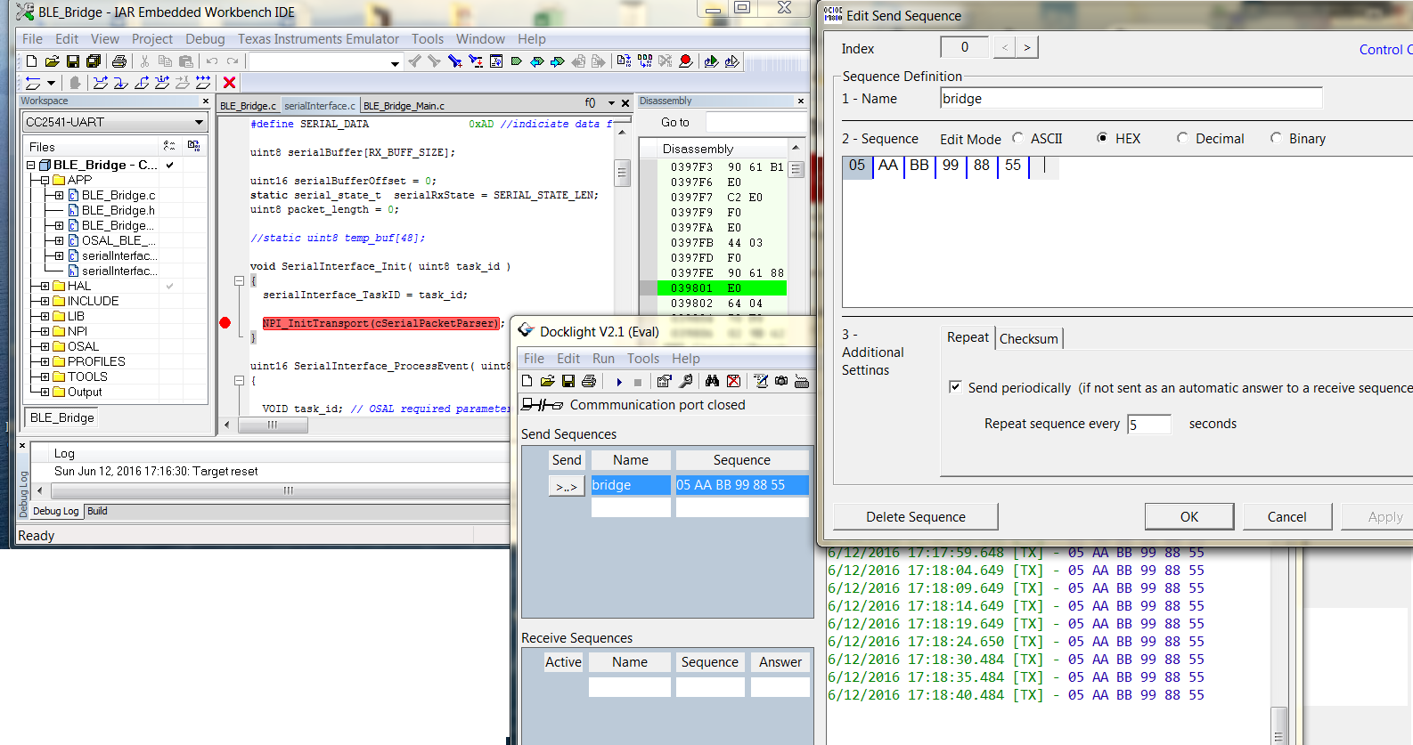
How to test CC2541 (uart communication to pc or mcu )serial BLE_Bridge
with usb cc2540 dongle using BTool???Pls suggest the steps to be followed w.r.to BTool
Currently i am refering this link :- http://processors.wiki.ti.com/index.php/SerialBLEbridge
I am doing the project to send data from server CC2541EM (on SmartRF05EB) to client CC2540 dongle using SerialBLEbridge software.
I have same questions about how to test the SerialBLEbridge software and really need to find answer ASAP to identify
the right solution for prototype the product.
Hi,
Lets say you have the following setup.
1) SimpleBLEbridge application running on CC2541 EM module connected to smartRF05EB board. UART cable from SmartRF05EB is connected to PC serial port. You have an application like Dock light or Tera term which is opened in your PC with correct COM port and Baud rate of 115200.
2) You have a CC2540 USB dongle connected to a PC running BLE device monitor or BTool.
Now the moment you power up the CC2541EM board which runs BLE bridge application, it starts advertising, You can start scanning in your CC2540USB dongle using BLE device Monitor. Once the device is found, please connect to it. Please discover all services and read all chars. Check specifically the value of Char 4 in simple Keys profile. Enable notification for Char 4.
Now from the serial port send Hexadecimal commands(you can use Dock light application for this) to CC2541EM running BLE Bridge is the format Len->Payload i.e 1st Byte is Length followed by that many bytes of Payload data(e.g. 05:AA:BB:99:88:55 where 05 denotes the len and the payload is AA:BB:99:88:55). This payload should get reflected in Char 4 on BLE device monitor. You will also get an ACK back on your serial port in the format AB A5 <Num_bytes_of_payload_sent>
Now you can write a single byte value to Char 3, this should get reflected in your serial port as AB: AD: <Value>
Regards,
Arun
Hi Arun,
I have followed your suggestions to test “SimpleBLEBridge”, now am putting my work progress and questions.
- I have smartRF05EB board and CC2540 USB dongle on same PC. Is it all right those two devices on same PC?
- I use Dock light to send sequence from Server, and BTool to receive notification on Client.
- Click “scan” (device found 1), “establish”. I assume two devices have connected successfully, although SmartRF05EB doesn’t set for displaying the “connected” message which does for “SimpleBLEPeripheral” project.
- Discovery the CHAR4 handle, and write “01:00” to 0x002F (You mentioned “simple Keys profile”, do you actually mean “SimpleGATTprofile”? I did not see “simple Keys profile” in SerialBLEbridge project). The step is for receiving the notification from server. I assume it has done now.
- Open Dock Light with related COM, send “05:AA:BB:99:88:55” sequence. But I don’t know if it is actually sent out or not, because I cannot see any Notification value on BTool. (The Notification value “03” is shown if testing the “SimpleBLEPeripheral” software).
- I am new to Dock Light, is it possible to give more details about the setting for Dock light?
- Is it right to say the payload “AA:BB:99:88:55” sent from sever will be displayed in the log area on BTool if “success” ( It is “03” for SimpleBLEPeripheral”)?
I need helps to make project going ASAP. Thank you.
Hi,
1) Yes. you can use both smartRF05EB board and CC2540USB dongle on same PC. They will be connected to different ports in your PC.
2) I would suggest using BLE device Monitor instead of Btool. It would be easier to see/edit change of value than Btool.
3) There is no LCD in BLE Bridge application. so nothing will be seen on LCD of smartRF05EB board.
4) Sorry. I meant simpleGATT profile only. You need to edit the Client characteristic configuration descriptor of Char 4. I hope you have done it.
5) In docklight you need to establish a connection first. Give the correct Baud rate(115200) and serial port and starta connection. The you can write custom commands in docklight. Check some documentation on how to do it. When you send commands, put a break point in cSerialPacketParser to see if you received the command.
6) This value should updated on Char 4. Check BLE device monitor to get updated value.
Regards,
Arun
Hi Arun, Thank you for your reply.
- First, I am using “BLE device monitor” with “SimpleBLEPeripheral”project to test if the client can receive the notification data from Server. It works OK from the log file on “Device Monitor”
12:16:06.745 > BLE Host: COM5 baud 115200 flowc. no
12:16:06.788 > HCI_Ext_Build_Revision: status=00 Rev=35955
12:16:06.788 > BLE Host TI BLEv1.4 CC254x
12:16:06.798 > HCI_Ext_Reset_System: status=00
12:16:07.300 > GAP Device Init Done
12:16:07.300 > BLE Host initialised
12:16:07.305 > Scan request ...
12:16:07.306 > HCI_Ext_Overlapped_Processing: status=00
12:16:16.099 > GAP Device Information: status=0 type=0x00 [len=7]
12:16:16.101 > MAC address (ind. adv): 78:C5:E5:6E:52:68
12:16:16.102 > Scan resp: ad=0x01 len=2
12:16:16.102 > Scan resp: ad=0x02 len=3
12:16:16.120 > GAP Device Information: status=0 type=0x04 [len=30]
12:16:16.120 > MAC address (scan. resp): 78:C5:E5:6E:52:68
12:16:16.121 > Device found: SimpleBLEPeripheral
12:16:16.121 > Scan resp: ad=0x12 len=5
12:16:16.122 > Scan resp: ad=0x0a len=2
12:16:17.560 > Scan finished [10.256 sec]
12:16:17.561 > GAP Device Discovery: 1 device(s), status=0x00
12:16:21.771 > Connect request
12:16:21.958 > Gap Link Established: h=0 ci=16 lat=0 to=50
12:16:21.958 > SimpleBLEPeripheral connected
12:16:21.963 > Service discovery started
12:16:22.005 > ReadByGrpTypeRsp: status=0 n=19
12:16:22.044 > ReadByGrpTypeRsp: status=0 n=7
12:16:22.050 > ReadByGrpTypeRsp: status=26 n=0
12:16:22.050 > Primary Service Discovery done [0.90 sec]
12:16:22.061 > Characteristic description discovery started
12:16:22.105 > FindInfoRsp: status=0 n=21
……………………….
12:16:22.505 > FindInfoRsp: status=0 n=5
12:16:22.544 > FindInfoRsp: status=26 n=0
12:16:22.544 > Characteristic Description Discovery done [0.483] sec
12:16:22.547 > Characteristic discovery started
12:16:22.585 > ReadyByTypeResp: status=0 n=22
12:16:22.625 > ReadyByTypeResp: status=0 n=22
………………………….
12:16:22.785 > ReadyByTypeResp: status=0 n=22
12:16:22.825 > ReadyByTypeResp: status=0 n=15
12:16:22.864 > ReadyByTypeResp: status=26 n=0
12:16:22.864 > Characteristic Discovery done [0.317] sec
12:16:28.103 > GAP Link Param Update: 0 0 800 0 1000
12:16:28.103 > Connection parameters updated
12:16:36.706 > ReadCharValue[2902]
12:16:38.123 > ReadResp[2902]: status=0 n=2, 00 00
12:16:44.891 > WriteCharValue[2902]: v=0001
12:16:44.892 > Attr edited, 47 01:00
12:16:46.124 > WriteRsp[2902]: status=0 n=0
12:16:49.123 > Notification[FFF4]: status=0 n=1 08
12:16:54.123 > Notification[FFF4]: status=0 n=1 08
12:16:59.124 > Notification[FFF4]: status=0 n=1 08
12:17:04.124 > Notification[FFF4]: status=0 n=1 08
12:17:09.123 > Notification[FFF4]: status=0 n=1 08
12:17:14.124 > Notification[FFF4]: status=0 n=1 08
12:17:19.124 > Notification[FFF4]: status=0 n=1 08
- But no luck trying to send a sequence (05:AA:BB:99:88:55) from Dock Light, as I cannot see any “Notification”. What I did is simply defining the “Port” and editing the “send sequence”, then “send”.
- I don’t understand what you said “Then you can write custom commands in docklight. Check some documentation on how to do it. When you send commands, put a break point in cSerialPacketParser”. I only have “Dock Light 2.0 Evaluation” installed. Would it be used to do what you said?
- I downloaded “SimleBLEbridge” project and results are same.
- 12:28:45.391 > BLE Host: COM5 baud 115200 flowc. no
12:28:45.405 > HCI_Ext_Build_Revision: status=00 Rev=35955
12:28:45.405 > BLE Host TI BLEv1.4 CC254x
12:28:45.412 > HCI_Ext_Reset_System: status=00
12:28:45.916 > GAP Device Init Done
12:28:45.916 > BLE Host initialised
12:28:45.920 > Scan request ...
12:28:45.921 > HCI_Ext_Overlapped_Processing: status=00
12:28:45.975 > GAP Device Information: status=0 type=0x00 [len=3]
12:28:45.975 > MAC address (ind. adv): 78:C5:E5:6E:52:68
12:28:45.975 > Scan resp: ad=0x01 len=2
12:28:45.987 > GAP Device Information: status=0 type=0x04 [len=18]
12:28:45.987 > MAC address (scan. resp): 78:C5:E5:6E:52:68
12:28:45.987 > Device found: SJM.EPG
12:28:45.988 > Scan resp: ad=0x12 len=5
12:28:45.988 > Scan resp: ad=0x0a len=2
12:28:56.178 > Scan finished [10.258 sec]
12:28:56.179 > GAP Device Discovery: 1 device(s), status=0x00
12:29:05.041 > Connect request
12:29:05.156 > Gap Link Established: h=0 ci=16 lat=0 to=50
12:29:05.156 > SJM.EPG connected
12:29:05.161 > Service discovery started
12:29:05.201 > ReadByGrpTypeRsp: status=0 n=19
12:29:05.240 > ReadByGrpTypeRsp: status=0 n=7
12:29:05.245 > ReadByGrpTypeRsp: status=26 n=0
12:29:05.246 > Primary Service Discovery done [0.88 sec]
12:29:05.258 > Characteristic description discovery started
12:29:05.301 > FindInfoRsp: status=0 n=21
12:29:05.341 > FindInfoRsp: status=0 n=21
12:29:05.381 > FindInfoRsp: status=0 n=21
12:29:05.421 > FindInfoRsp: status=0 n=21
12:29:05.461 > FindInfoRsp: status=0 n=21
12:29:05.501 > FindInfoRsp: status=0 n=21
12:29:05.541 > FindInfoRsp: status=0 n=21
12:29:05.581 > FindInfoRsp: status=0 n=21
12:29:05.621 > FindInfoRsp: status=0 n=21
12:29:05.661 > FindInfoRsp: status=0 n=21
12:29:05.701 > FindInfoRsp: status=0 n=5
12:29:05.740 > FindInfoRsp: status=26 n=0
12:29:05.740 > Characteristic Description Discovery done [0.482] sec
12:29:05.743 > Characteristic discovery started
12:29:05.781 > ReadyByTypeResp: status=0 n=22
12:29:05.821 > ReadyByTypeResp: status=0 n=22
……………………………
12:29:05.981 > ReadyByTypeResp: status=0 n=22
12:29:06.021 > ReadyByTypeResp: status=0 n=15
12:29:06.060 > ReadyByTypeResp: status=26 n=0
12:29:06.060 > Characteristic Discovery done [0.317] sec
12:29:22.629 > ReadCharValue[2902]
12:29:22.660 > ReadResp[2902]: status=0 n=2, 00 00
12:29:29.654 > WriteCharValue[2902]: v=0001
12:29:29.655 > Attr edited, 47 01:00
12:29:29.700 > WriteRsp[2902]: status=0 n=0
- I felt I am half way to get the final results. Could you give more detailed steps how to sending the sequence successfully by Dock Light.
Thank you.
Hi Arun,
A) On the instruction 5) you wrote, “In docklight you need to establish a connection first. Give the correct Baud rate(115200) and serial port and starta connection. Then you can write custom commands in docklight. Check some documentation on how to do it. When you send commands, put a break point in cSerialPacketParser to see if you received the command.”
B) Here are the steps I use on Docklight 2.0 script (EVA)
2. Communication mode: Send/Receive.
3. COM =5 baud rate=115200, data bits=8, stop bits =1, parity=ignored
4. “Send Sequence” definition. Name: bridge, sequence: 05:AA:BB:99:88:55 (Hex)
5. Did not defining the “Receive Sequences”
6. Run “Start Communication”
7. Click “Send”
8. Messages shown in the communication window: 15/10/2014 10:36:28.056 [TX] – 05 AA BB 99 88 55
B) But above message, AA:BB:99:88:55, can’t be seen in “BLE Device Monitor”, so that I don’t know whether the data has received or not.
C) It seems that I didn’t get correct way to send data from DockLight. I use “Docklight 2.0 script EVALUATION, is it OK?
D) Does RS232 cable have to be from Docklight http://www.docklight.de/info_en.htm#dl_info_adapter? I use standard RS232 cable.
E) If possible, could you give a sample application as starting point to make Dock Light working: sending data and can been reflected somewhere?
F) Do you suggest to use IAR to debug/download “SerialBLEbridge” software?
Thank you.
Hi,
Have you made sure that flow control is disabled on BLE_Bridge application? you can turn this off by changing NPI_UART_FC to FALSE in npi.h. Please compile after this change and flash it to CC254x device. By default this application access UART_PORT_0 using P0 pins.
Btw, which device are you working on? CC2541 sensor tag or CC2540 EM board or CC2540 USB module? I am asking this because in CC2541 sensor tag the USART port 0 is bought out on P1 pins and P0 pins are not exposed. Hence for sensor tag module more changes are required,
But on CC2540 EM module this should work straight way with flow control disabled.
I suggest you start a debug session on IAR first with CC254x device after flashing BLE_Bridge application. The put a break point at cSerialPacketParser() function call. This is the function call triggered by UART DMA when it receives bytes on UART Rx channel. If you are hitting this break point when you send data from dock light, application then your UART Rx configuration should be fine,
Your configuration of dock light seems fine. Please check the points I have mentioned earlier and let us know of the result.
Regards.
Arun
I use CC2541EM, as some people mentioned about the issue if using CC2540EM.
http://e2e.ti.com/support/wireless_connectivity/f/538/p/346477/1229534.aspx#1229534
The SerialBLEbridge software is written for CC2541EM. I am not sure what are the changes for IAR if using CC2540EM.
I have CC2540EM and CC2541EM. Can you instruct which one is more convinence in term of making changes.
Thank you.
Hi,
You can use the CC2541EM. Just disable Flow Control as I mentioned earlier in NPI.h. No other changes should be required.
Regards,
Arun
Hi Arun
Thank you
Hi,
I would suggest start a download and debug session in IAR fisrt. Put the break point in the code even before starting execution. Only after this you start execution.
Now, you should be able to hit the break point when you write 05:AA:BB:CC:DD:EE through dock light(Make sure that BLE device monitor is connected before this step).
If you are hitting the break point properly, next time please disable the break point and check if the send data is reflected on BLE device monitor.
Regards,
Arun
Hi Arun,
It is working. Thank you for your good instructions that really useful!
I am going to look at how to use SerialBLEbridge to transmit data in a file.
Thanks a lot.
Is it possible to use the RF06EB with the CC2541, instead of the RF05EB?
~Leonard
Hi Leonard,
In the aspect of accessing peripherals, I pressume so. However, the onboard debugger is XDS100 JTAG so you would not be able to flash/debug with it.
Best Regards
Joakim
Hi,
thanks for this tutorial. but in my case it doesnt work as I excepted. It works to send data from Dock Light and CC2541EM to USB dongle. But when I want to send data from USB dongle I write a number (for example 14)to Char3 to device monitor and then I was expected something like AB AD 5.. but i received AB AD 00 12 02 85 03? Is it correct? If yes, how do decode it?
Thanks,
Jan
Hello,
I am sorry for disturbing you. I am working in a project and I am very close to the solution. I use the BLE_Bridge example.
Please anyone to help me to understand which option settings I should use in order to have UART communication and how can verify that there is communication between cc2540BLE board and my PC (these are connected with a RS232-to-USB cable).
Secondly, which preprocessing options I should use in order to have advertisement of the BLE name , again concerning the BLE Bridge example.
Please any help as soon as possible?
Thank you in advance,
Dear Mr. Arun Menon,
Hello. I am sorry for disturbing you.
I follow your instructions but this issue is not solved. I am working on BLE_Bridge-UART with its preprocessor settings, where the port 0 is used.
[1] Firstly, I connect my PC with the cc2540 BLE board (BLE112), using an FTDI uart-toUSB converter. Tx of FTDI with P0.2, Rx with P0.3 , GND with GND, without using flow and th other pins of FTDI.
[2] I use the docklight , I set 115200 baud rate in COM11 where my FTDI is connected. And every 5 sec I send 05 AA BB 99 88 85 . And also I add the breakpoint in the function call "NPI_InitTransport(cSerialPacketParser);" of SerialInterface_Init() function of serialInterface.c file . Am I right?
I CANNOT SEE any response (receive sequence in docklight) by cc2540!!!!
Why? Where I am wrong? COULD YOU PLEASE HELP ME in order for me to proceed my project?
Thank you in advance,