Other Parts Discussed in Thread: CC2640
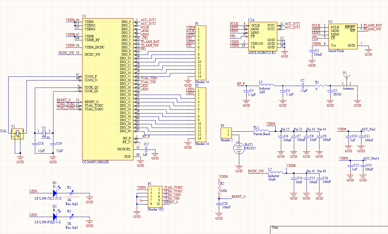
I am using the CC-DEVPACK-DEBUG with 7x7mm CC2640 on a custom board. The pcb is milled and hand soldered so HW could be an issue but Ref designs were followed exactly. I have checked that all the correct pins are connecting to the debugger. I was getting the following error when test target connection:
[Start: Texas Instruments XDS110 USB Debug Probe_0]
Execute the command:
%ccs_base%/common/uscif/dbgjtag -f %boarddatafile% -rv -o -S integrity
[Result]
-----[Print the board config pathname(s)]------------------------------------
C:\Users\Cam\AppData\Local\TEXASI~1\CCS\
ti\1\0\BrdDat\testBoard.dat
-----[Print the reset-command software log-file]-----------------------------
This utility has selected a 100- or 510-class product.
This utility will load the adapter 'jioxds110.dll'.
The library build date was 'Jul 23 2015'.
The library build time was '19:45:35'.
The library package version is '6.0.14.0'.
The library component version is '35.35.0.0'.
The controller does not use a programmable FPGA.
The controller has a version number of '5' (0x00000005).
The controller has an insertion length of '0' (0x00000000).
This utility will attempt to reset the controller.
This utility has successfully reset the controller.
-----[Print the reset-command hardware log-file]-----------------------------
The scan-path will be reset by toggling the JTAG TRST signal.
The controller is the XDS110 with USB interface.
The link from controller to target is direct (without cable).
The software is configured for XDS110 features.
The controller cannot monitor the value on the EMU[0] pin.
The controller cannot monitor the value on the EMU[1] pin.
The controller cannot control the timing on output pins.
The controller cannot control the timing on input pins.
The scan-path link-delay has been set to exactly '0' (0x0000).
An error occurred while hard opening the controller.
-----[An error has occurred and this utility has aborted]--------------------
This error is generated by TI's USCIF driver or utilities.
The value is '-241' (0xffffff0f).
The title is 'SC_ERR_ROUTER_SECURE_SUBPATH'.
The explanation is:
A router subpath could not be accessed.
A security error has probably occurred.
[End: Texas Instruments XDS110 USB Debug Probe_0]
I then raised the supply voltage from 3V (CR2032) to 3.3V. I'm not sure how that made a difference but I am getting this error now.
[Start: Texas Instruments XDS110 USB Debug Probe_0]
Execute the command:
%ccs_base%/common/uscif/dbgjtag -f %boarddatafile% -rv -o -S integrity
[Result]
-----[Print the board config pathname(s)]------------------------------------
C:\Users\Cam\AppData\Local\TEXASI~1\CCS\
ti\1\0\BrdDat\testBoard.dat
-----[Print the reset-command software log-file]-----------------------------
This utility has selected a 100- or 510-class product.
This utility will load the adapter 'jioxds110.dll'.
The library build date was 'Jul 23 2015'.
The library build time was '19:45:35'.
The library package version is '6.0.14.0'.
The library component version is '35.35.0.0'.
The controller does not use a programmable FPGA.
The controller has a version number of '5' (0x00000005).
The controller has an insertion length of '0' (0x00000000).
This utility will attempt to reset the controller.
This utility has successfully reset the controller.
-----[Print the reset-command hardware log-file]-----------------------------
The scan-path will be reset by toggling the JTAG TRST signal.
The controller is the XDS110 with USB interface.
The link from controller to target is direct (without cable).
The software is configured for XDS110 features.
The controller cannot monitor the value on the EMU[0] pin.
The controller cannot monitor the value on the EMU[1] pin.
The controller cannot control the timing on output pins.
The controller cannot control the timing on input pins.
The scan-path link-delay has been set to exactly '0' (0x0000).
-----[An error has occurred and this utility has aborted]--------------------
This error is generated by TI's USCIF driver or utilities.
The value is '-233' (0xffffff17).
The title is 'SC_ERR_PATH_BROKEN'.
The explanation is:
The JTAG IR and DR scan-paths cannot circulate bits, they may be broken.
An attempt to scan the JTAG scan-path has failed.
The target's JTAG scan-path appears to be broken
with a stuck-at-ones or stuck-at-zero fault.
[End: Texas Instruments XDS110 USB Debug Probe_0]
It may not be hardware but if it is, what voltages should I be getting at the pins before and after connecting the debugger on a chip that has never been programmed before?