This thread has been locked.

If you have a related question, please click the "Ask a related question" button in the top right corner. The newly created question will be automatically linked to this question.

I2C runt / short cycles in BIM modification

Other Parts Discussed in Thread: BLE-STACK, CC2640

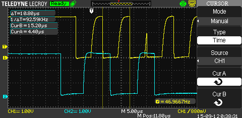
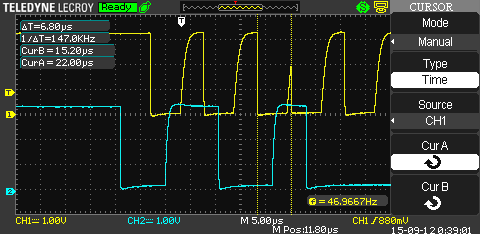
I'm in the process of modifying the BIM included with BLE-Stack 2.1 for an I2C memory instead of SPI.  However, when using the I2C master in the cc2640, we are seeing some short-cycling on the SCL output, which is leading to read/write errors and occasionally a stuck bus. It happens at both 100KHz and 400KHz I2C speeds.

Measurement of a normal cycle:
Measurement of the short cycle:
Since it's the boot loader, it's pretty much bare-metal code - single process, plenty of delays to let supplies settle and whatnot. The power supplies look good and stable. I've verified that the cc2640 is configured to use the external LF OSC. Here's what the code in concern looks like:

I2CMasterSlaveAddrSet(BLS_I2C_BASE, 0b1010000, false);// true = about to issue a receive, false= about to issue a write.

I2CMasterDataPut(BLS_I2C_BASE,(addr & 0xFF));// first address word

I2CMasterControl(BLS_I2C_BASE, I2C_MASTER_CMD_BURST_SEND_START);// sends a byte..

while(I2CMasterBusy(BLS_I2C_BASE));

...

Seems straight forward enough. Any ideas what could be causing the glitched clock output from the I2C peripheral?

Thanks,

Art

  • Hi Art,

    I agree the logic should be straight forward. However, can you share here the whole process that you have made including initialization so that we can reproduce the problem if necessary?

    - Cetri

  • Hy there. Any news on this? I am dealing with the same issue at the moment. Well, not the clock issues on SCL but modifying BIM for reading an external I2C eeprom rather than an extern SPI Flash. (see e2e.ti.com/.../456866) Maybe you could post a larger portion of your code: How do you init IO Pins and I2C? How does your eeprom read function look like? How did you overcome the "loosing clock cycles" issue?
    Best regards
    Harald

  • Art,

    Are there any interrupts occuring that might be writing / reconfiguring anything while using the I2C module? You can try to wrap the function calls in the instructions CPUcpsid() / CPUcpsie() from driverlib/cpu.h to rule out this as a cause.

    Regards,
    Svend
  • No interrupts running. Here's the entire main.c:

    /*******************************************************************************
    Filename: bim_main.c
    *******************************************************************************/

    /* -----------------------------------------------------------------------------
    * Includes
    * -----------------------------------------------------------------------------
    */
    #include <stdint.h>
    #include <string.h>
    #include <driverlib/flash.h>
    #include <driverlib/watchdog.h>
    #include <inc/hw_prcm.h>

    #include "hal_flash.h"
    #include "bls.h"
    #include "ext_flash_layout.h"
    #include "oad_target.h"

    /* -----------------------------------------------------------------------------
    * Constants
    * -----------------------------------------------------------------------------
    */

    #define BIM_IMG_E_OSET OAD_IMG_E_OSET
    #define BASELOADER_IPAGESIZE 4096


    /*******************************************************************************
    *
    *******************************************************************************/
    #include <driverlib/ssi.h>
    #include <driverlib/gpio.h>
    #include <driverlib/prcm.h>
    #include <driverlib/ioc.h>
    #include <driverlib/rom.h>
    #include <driverlib/ssi.h>
    #include <driverlib/i2c.h>
    #include "bsp.h"
    #include "bsp_spi.h"

    #define BLS_SPI_BASE SSI0_BASE
    #define BLS_I2C_BASE I2C0_BASE //base address of hw regs for i2c
    #define BLS_CPU_FREQ 48000000ul
    #define BLS_FAST_I2C false
    #define BLS_I2C_BYTEDELAY 500 // 500 = ~10 usec for fast mode, 2000 = ~40usec for slow mode.
    #define BLS_I2C_TIMEOUT 5000 // cylces to wait

    #define BLS_I2C_SLAVE_ADDR 0b10100000


    #define BLS_PIN_SDA IOID_4
    #define BLS_PIN_SDA_MASK 0x00000010 // 0b00000000 00000000 00000000 00010000
    #define BLS_PIN_SCL IOID_8
    #define BLS_PIN_SCL_MASK 0x00000100 // 0b00000000 00000000 00000001 00000000
    #define BLS_I2C_POWER IOID_1 // as of PCB rev 1.3...

    uint8_t I2C_DataOut;
    uint8_t I2C_DataIn;


    /*******************************************************************************
    * Actual function to load image.
    *
    * @brief Before entering this function, interrupts must be disabled and
    * stack pointer must be set correctly.
    *
    * @param start - image start address in external flash.<br>
    * Must be 4 byte aligned address.
    * @param len - length of the image in bytes.
    * @param dstaddr - address in internal flash to where to start writing
    * the image.<br>
    * Must be 4 byte aligned address.<br>
    * Note that when dstaddr is not internal flash page boundary
    * aligned, all preceding words in the same page will be
    * erased.
    *
    * @return none
    */
    void Bim_safeStart(uint32_t start, uint32_t len, uint32_t dstAddr)
    {
    // Initialize external flash driver.
    //BLS_init();

    // Copy over the image. Note that failure cannot be handled.
    //Bim_copyImage(start, len, dstAddr);

    // Close external flash driver.
    //BLS_close();

    // Trigger reset.
    HWREG(PRCM_BASE + PRCM_O_WARMRESET) = 4;
    WatchdogResetEnable();
    WatchdogEnable();
    WatchdogReloadSet(0);

    // Enable reset interrupt.
    CPUcpsie();

    // Stay here till reset.
    for (;;);
    }

    uint32_t bspI2CRandomW(uint32_t addr, uint8_t data)
    {
    uint32_t I2CError = I2C_MASTER_ERR_NONE;
    uint8_t tempReadBack =0;
    uint32_t timeoutCounter = 0;

    I2CMasterSlaveAddrSet(BLS_I2C_BASE, 0b1010000, false);// true = about to issue a receive, false= about to issue a write.

    I2CMasterDataPut(BLS_I2C_BASE,(addr & 0xFF));// first address word
    I2CMasterControl(BLS_I2C_BASE, I2C_MASTER_CMD_BURST_SEND_START);// sends a byte..
    CPUdelay(BLS_I2C_BYTEDELAY); // roughly 10 usec..

    I2CError = I2CMasterErr(BLS_I2C_BASE);

    if (I2CError == I2C_MASTER_ERR_NONE)
    {
    I2CMasterDataPut(BLS_I2C_BASE,((addr>>8) & 0xFF));// second address word
    I2CMasterControl(BLS_I2C_BASE, I2C_MASTER_CMD_BURST_SEND_CONT);

    I2CError = I2CMasterErr(BLS_I2C_BASE);
    if (I2CError == I2C_MASTER_ERR_NONE)
    {
    I2CMasterDataPut(BLS_I2C_BASE, data); // byte to write.
    I2CMasterControl(BLS_I2C_BASE, I2C_MASTER_CMD_BURST_SEND_FINISH);
    CPUdelay(BLS_I2C_BYTEDELAY); // roughly 10 usec..
    I2CError = I2CMasterErr(BLS_I2C_BASE);
    }
    }

    CPUdelay(0x03A980);

    if (I2CError != I2C_MASTER_ERR_NONE)
    { // force a stop somehow...

    }
    return I2CError;

    } // end bspI2CRandomWrite


    void main(void)
    {
    uint32_t metaDataAddr;
    uint8_t tempData =0;

    //======= in-lined from I2C Open ====
    /* GPIO power && SPI power domain */
    PRCMPowerDomainOn(PRCM_DOMAIN_PERIPH | PRCM_DOMAIN_SERIAL);
    while (PRCMPowerDomainStatus(PRCM_DOMAIN_PERIPH | PRCM_DOMAIN_SERIAL) != PRCM_DOMAIN_POWER_ON);

    /* GPIO power */
    PRCMPeripheralRunEnable(PRCM_PERIPH_GPIO);
    PRCMLoadSet();
    while (!PRCMLoadGet());

    /* I2C (not SPI) power */
    ROM_PRCMPeripheralRunEnable(PRCM_PERIPH_I2C0);
    PRCMLoadSet();
    while (!PRCMLoadGet());

    IOCPinTypeGpioOutput(BLS_I2C_POWER);
    IOCIODrvStrengthSet (BLS_I2C_POWER, IOC_CURRENT_8MA, IOC_STRENGTH_MAX);
    HWREG(GPIO_BASE + GPIO_O_DOE31_0) |= (1 << (BLS_I2C_POWER)); // turn on the output enable
    HWREG(GPIO_BASE + GPIO_O_DOUTSET31_0) = (1 << (BLS_I2C_POWER)); // set the output value to 1.
    // wait for flash to power up...
    CPUdelay(0x493E00);//0x927C00 = 200 msecs. 0x03A980 = 5msec, 0x493E00 = 100 msec,

    I2CMasterIntDisable(BLS_I2C_BASE);
    I2CMasterIntClear(BLS_I2C_BASE);

    I2CMasterInitExpClk(BLS_I2C_BASE, BLS_CPU_FREQ, BLS_FAST_I2C); // (uint32_t ui32Base, uint32_t ui32I2CClk, bool bFast)

    IOCPortConfigureSet(BLS_PIN_SDA, IOC_PORT_MCU_I2C_MSSDA, IOC_IOMODE_OPEN_DRAIN_NORMAL | IOC_IOPULL_UP | IOC_HYST_ENABLE);
    IOCPortConfigureSet(BLS_PIN_SDA, IOC_PORT_MCU_I2C_MSSCL, IOC_IOMODE_OPEN_DRAIN_NORMAL | IOC_IOPULL_UP | IOC_HYST_ENABLE);

    IOCPinTypeI2c(BLS_I2C_BASE, BLS_PIN_SDA, BLS_PIN_SCL);

    // do a test write
    bspI2CRandomW(0x000004, 0x24);// Start Random Write. - note data is now a pointer...

    // Power down
    ROM_PRCMPeripheralRunDisable(PRCM_PERIPH_I2C0);
    PRCMLoadSet();
    while (!PRCMLoadGet());

    PRCMPeripheralRunDisable(PRCM_PERIPH_GPIO);
    PRCMLoadSet();
    while (!PRCMLoadGet());

    PRCMPowerDomainOff(PRCM_DOMAIN_SERIAL | PRCM_DOMAIN_PERIPH);
    while (PRCMPowerDomainStatus(PRCM_DOMAIN_SERIAL | PRCM_DOMAIN_PERIPH)
    != PRCM_DOMAIN_POWER_OFF);

    // Load address of reset function from the fixed location of the image's
    // reset vector and jump.
    asm(" MOV R0, #0x1014 ");
    asm(" LDR R0, [R0] ");
    asm(" BX R0 ");

    }
    /**************************************************************************************************
    */
  • My solution was to just write a bit-banged I2C driver and keep moving forward....
  • Ignore my "// Start Random Write. - note data is now a pointer..." comment, I had to regress my code to give you guys something to work with. There may be other comments, defines, or variables that aren't applicable.