This thread has been locked.

If you have a related question, please click the "Ask a related question" button in the top right corner. The newly created question will be automatically linked to this question.

CC2640R2F: Flashing external target using Launchpad CC6240R2

Part Number: CC2640R2F
Other Parts Discussed in Thread: UNIFLASH

Hi,

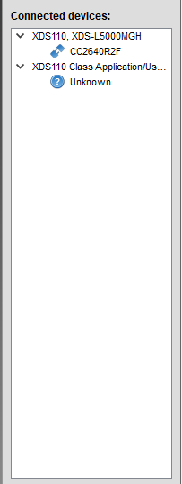
We are new to TI's chips and are trying to flash a custom board that is build around the CC2640R2F 48 pin. 
I've removed the jumper block in the center of the launchpad and connected TMSC, TCKC, TDO, TDI and Reset on the top row of the pin block. 

I'm using CCS Cloud to try and programme our board which worked fine for programming the Launchpad itself. 
However, now I'm getting the following error:

Error connecting to the target: (Error -242 @ 0x0) A router subpath could not be accessed. The board configuration file is probably incorrect. (Emulation package 8.0.27.9)

Is there any step I failed to do or does this indicate an hardware issue on our board?

Thanks!

  • - Could you try open SmartRF Studio or Flash Programmer 2 and see if you get the same error message when trying to connect?
    - Could you post a picture that clearly show how you have done the connection? It sounds correct but a picture will confirm.
    - Have you measured the current consumption of your custom board?
    - Have you verified that VDDR, DCOUPL have the expected voltages?
  • Thanks for your response.

    I'm working on a Mac so I've booted windows as a virtual machine and installed flash programmer 2. 
    I was unable to connect with the following error:

    ------------

    >Initiate access to target: COM4.
    >No response from device. Device may not be in bootloader mode. Reset device and try again.
    If problem persists, check connection and baud rate.
    >Connecting over serial bootloader failed: No response from device. Device may not be in bootloader mode. Reset device and try again.
    If problem persists, check connection and baud rate.
    >Failed to create device object.

    ------------

    Here's a photo album with pictures of the setup. I later tried to flash the cc2640R2F onboard using the same pins on the header block.
    This failed in the same way as our custom board.

    - I have not measured current consumption as the board currently has no power source. I was hoping to power it from the Launchpad. 

    - I'm unsure how to verify the VDDR, DCOUPL voltages. 

    Thanks in advance!

  • Hi,

    The signals you need to connect to your custom board are nRESET, TMS, TCK, and GND. I am doing this right now to a TI Reference Design Board.

    -kel
  • I could not see any photo album of your setup.

    It looks from your error message that you are trying to connect over the UART and not jtag. If that is the case, do you have a valid image on the chip or not?

    DCOUPL: Should be ~1.25 V
    VDDR: Should be 1.65 V
  • Apologies I must have done something wrong when adding the link, please view it here: photos.app.goo.gl/RehMTAbMSELWEk1L9
    There is no image on the chip yet (unless there something by default from the factory)
  • He Kel,

    Thanks for chipping in. Is your board externally powered by any chance?
  • As far as I can see you are not using gnd in the UART connection. If that is the case, try to add to ensure that the debugger has the same potential as the board you are trying to connect to.
  • Ok will do. I assume I will also have to connect the 3V line to have it powered by the launchpad?
  • The power connection will depend on which voltage you are using to power your custom board. If the voltage on the debugger and the custom board are equal you don't have to include an extra line. The easiest in this situation will likely be to supply the custom board from the debugger.
  • The board also requires 3V so based on your suggestions I have now connected: GND, 3V, Reset, TMS and TCK to the JTAG connect header. 
    See picture here

    Unfortunately the board will not programme in CCS cloud with the original error message:
    Error connecting to the target: (Error -242 @ 0x0) A router subpath could not be accessed. The board configuration file is probably incorrect. (Emulation package 8.0.27.9)

    Could you maybe explain to me how to flash using flash programmer over Jtag and not (which seems to be default) UART? 

    Thanks!

  • Hi,

    My target board is powered externally. See, my connections at the pic I shared in this post below.

    e2e.ti.com/.../725629

    -kel
  • user5376839: You ask about using flash programmer with default jtag. Are you here referring to flash programmer 2? I'm not aware of any of the tools that defaults to UART.

    You can also try Uniflash which has a mac version
  • Quick question: do I have to change anything on the project zero example to work on the 48 pin package I'm using?
  • I believe you ware referring to UART being used and it was also mentioned under "state" in flash programmer 2.

    I will checkout Uniflash.

    My goal is to flash one of the examples like simple peripheral or project zero to our custom board. Preferably using CCS cloud.

    We are using a JTAG-connect cable to interface with the board. The JTAG connect cable is connected to the Launchpad (see photo)

    We have 3.2V on the MCU and reset pin and internal dc-dc works. 

  • Hi,

       For 7x7 mm 48 pin package you can use the Launchpad board file. The SmartRF Flash Programmer 2 works. Have you seen my setup at my shared post. I have been programmin custom CC640R2F board more than 100x already and have done CCS debug. I suggest you to not depend on the CCS Cloud but rather use the latest CCS intalled to your PC.

       Here is what you need to do:

    1. Power your target board independently;

    2. Connect nRESET, TMS, TCK, GND from Launchpad to your Target Board.

    3. Power on your target board. Connect Launchpad USB to PC.

    After step 3 your Target board should be detected by the SmartRF Flash Programmer2. If not repeat step 3. If there is still problem then check you custom CC2640R2F board.

    -kel

  • user5376839: You wrote "Initiate access to target: COM4." which indicate UART. Why UART and not JTAG since not of the tools should default to UART?
  • He Kel,

    Yes, I've seen your setup it's technically identical to mine. 
    I've followed your steps but I'm getting different results, the connected devices will remain "Unkown"

    Please see this image

    We've double checked everything on the board and the hardware seems fine. We are getting the voltage, current draw seems correct and the DC-DC converter in the CC chip seems to work. 

    Thank you for your thoughts. 

  • He TER, What I did is the following:

    1. Connect the launchpad to my virtual machine running windows and flash programmer 2

    2. Manually selecting the target from the bottom left like so

    3. Right click "Unkown" under XDS110 class application and hit "connect" like so, this resulted in the aforementioned output. 

    I did not intend to connect over UART. It was just my novice attempt to start a connection. 

  • It should not be required to click connect. If everything is correct it should look like this in flash programmer 2:

    Then it's just to click on the chip name to get a connection with the device. 

  • I'm afraid I'm not getting that. Not even when I just connect the launchpad with all the standard bridges in place. (so no custom board connected)
  • But it recognize the XDS110 in the launchpad I hope? Could you post a screenshot of the same window as I did?
  • Hi,

       I also get "Unknown" at SmartRF Flash Programmer 2. When that happens I turn off power to target board and Launchpad. Then I do "3. Power on your target board. Connect Launchpad USB to PC.". My custom board is a TI Reference Design.

       The difference from my setup to yours is that it seems your powering your target board from the launchpad, based from your second shared picture.

    -kel

  • Yes it does see the launchpad. I've shared the image in an earlier post, here's the direct link: https://snag.gy/dmgDnc.jpg
  • He Kel,

    Yes I previously tried to power it from the board and started experimenting today with powering it externally.
    Good news, I finally did get it to work with CCS cloud. I will now upload firmware to our board.

    Many thanks for all your help.
  • user5376839: does this last post mean that I can close this thread?
  • Yes, thank you for all your help