This thread has been locked.

If you have a related question, please click the "Ask a related question" button in the top right corner. The newly created question will be automatically linked to this question.

Compiler/CC2640R2F: CC2640 crash

Part Number: CC2640R2F
Other Parts Discussed in Thread: LAUNCHXL-CC2640R2, CC2640,

Tool/software: TI C/C++ Compiler

PT01-V2.4.pdf1、We test the Bluetooth product part, touch the 32.768K crystal communication foot and reset it. When we thought it was a problem, we compared it with  LAUNCHXL-CC2640R2. It is the same situation. I don't know if it is a design problem or normal. Is there a solution?

2、Yesterday, I happened to find a problem. I touched the 24M crystal by hand. Under the charging condition, CC2640 sleeps and the device will crash. Both devices will appear, but not once touched. I need to touch more than once. One of them can't reset after crash. XDS110 can't recognize the chip, but according to XDS110, the reset lamp of the program still lights up.

3、Occasionally crash while charging equipment during sleepPT01-V2.4.pdfPT01_NA_V2.2.rar

  • I notice that you have mounted 12 pF load caps for the 24 MHz xtal. Does that mean you have turned off the internal load caps (See the crystal tuning chapter in www.ti.com/.../swra640.pdf )

    Could you give me some more context? Touching the xtal pins are not a normal use case and as you have discovered, could crash the chip since introducing a large load on one pin of the xtal could easily stop the xtal.
  • A total of 120 patches in small batches were tested on 20 patches. CC2640 did not sleep. Touching 24M crystal by hand would not kill the machine, but touching it 2-3 times during sleep would kill the machine. There are 3 pieces without 12 pf welded in 20 pieces.
  • A total of 120 patches in small batches were tested on 20 patches. CC2640 did not sleep. Touching 24M crystal by hand would not kill the machine, but touching it 2-3 times during sleep would kill the machine. There are 3 pieces without 12 pf welded in 20 pieces.

  • Sorry, could you please elaborate a few things:
    "A total of 120 patches in small batches were tested on 20 patches" Normally a patch is a software fix. Do you mean that 20 out of 120 boards did not sleep? And do you mean that 3 out of these 20 are without load caps for the 24 MHz xtal?
  • Thank you for your reply first. I generated 120 pcs, tested 20 pcs of them, and touched the 24M crystal with my handI generated 120 pcs, tested 20 pcs of them, and touched the 24M crystal with my hand when it was turned on.It will not crash,but in sleep state,it will crash with touching 2-3 times。
  • It's still not clear why you are touching the xtal in the first place? 

  • It will crash during charging in sleep state. it is not crash when the it is working。we test found that static electricity was generated when the charging wire was unplugged. so It's believed that the reason why you try to touch 24M with your hand is that it also crashes.
  • Do not touch the xtal pins since this could potentially destroy the device.

    If I understand the real issue correctly: Some of the devices will crash while in sleep.
    - What is VDDS before, under and after charging, is the voltage 3.3 V constant?
    - Which state is sleep?
    - How do you define crash/ how do you know if the chip has crashed?
  • 1. When the battery is 3.4V, the device will detect low power and go to sleep.
    2. Equipment batteries should always be higher than 3.3V. Power supply to CC2640 is regulated by LDO to 3.3V.
    3. Sleep: Enabling CC2640 to sleep by pressing a button。
    4. During the charging process, pull out the charging wire and trigger the button to wake up CC2640. It can not wake up. It can be re-run by reset.
  • Sleep, is that standby or shutdown?

    Could you share the part of the code that controls the wake up of the CC2640? Which button (with reference to the schematic) are you referring to?
  •  We use keys to control sleep and wake up to work. KEY use DIO18,
    CC2640 does not have direct sleep instructions, just shut down the application layer application into sleep. After triggering the button, we shut down all application layer applications and enter low power sleep.
    The code is as follows:
  • Does that mean that you are using the BLE stack?

    I believe that your code snippets show how you enter sleep but not how you use a button to exit sleep.
  • We found that the button didn't wake up it.I'll sort out the code and send it out later.

    There was also a device that did reset program after key wake-up, the device immediately crashed, and no reason was found. The reason why we wake up to do initialization interface is that Bluetooth sometimes can not be connected, reset can be done, so we initialized after key wake-up, remove the reset operation, and then the device will not crash, and actively connect Blue through APP. It takes two teeth to succeed.

  • Any progress on this case?
  • We have now added shield cover to test for 2 weeks and no more crash, but this is just to prevent static electricity from passing, I don't know if there are any other protective measures.

  • On Saturdays, we tested charging and discharging, and the equipment was normal.After work, we turn off our equipment and go to sleep. We can't turn it on on Monday. Normal after reduction.We tested four of them, and one of them showed this phenomenon.

  • There was a device crash this afternoon. During the sleep charging process, the buttons could not wake up the device.
  • I asked "I believe that your code snippets show how you enter sleep but not how you use a button to exit sleep." and you answered "I'll sort out the code and send it out later.". So far I have not seen any relevant code that could explain why you see a crash.
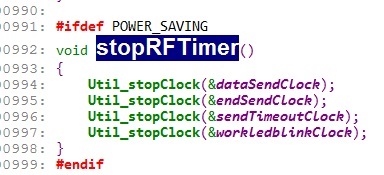
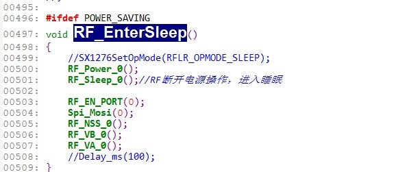
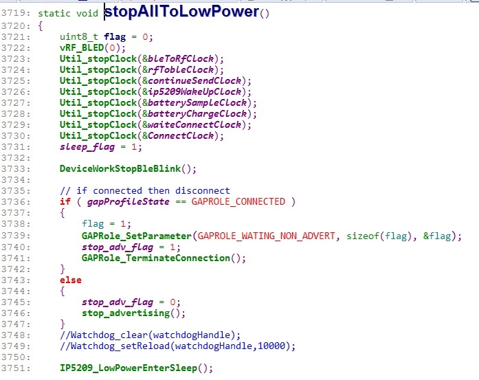
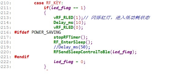
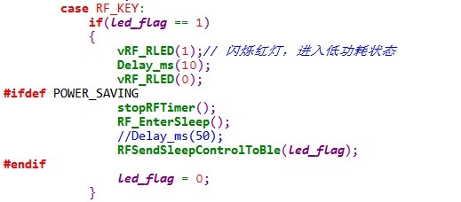
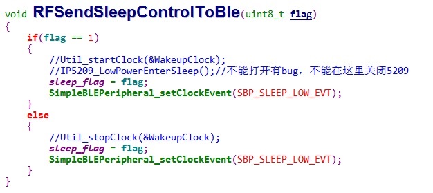
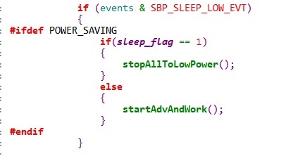
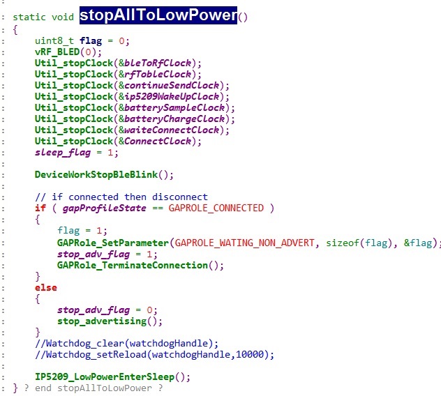
  •   Based on the low-power development data of CC2640R2F, devices need to enter the low-power interface without calling the system layer or protocol stack. They only need to define the POWER_SAVING macro definition in the compiler attributes. Then the application layer only needs to close the functions of timer, broadcasting, connection and so on. The system layer or protocol stack will work according to the application layer. Whether there is something to deal with to decide whether to enter the low power consumption, if the application layer does not have anything to deal with, it will enter the low power consumption, or even deep dormancy. The system layer or protocol stack detection part is the original processing in the sdk. This part has not been modified, it is all the original processing of the official.           

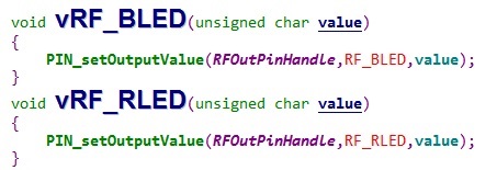
     In the actual development process, when the key press enters the low power consumption, the application layer will stop all the things being processed, and then the system layer or protocol stack will detect the automatic entry of low power consumption. After triggering the button, the application layer closes the code (application layer code, because the system layer or protocol stack has not changed, is SDK native, so the native code is not screenshot). The screenshot is as follows:

    The above code is the processing of the application layer before entering the low power consumption. The application layer does not call the interface of the system into the low power consumption, but closes the functions that need to be processed and automatically enters the low power consumption by the system itself.

    2. Wake-up from low power consumption:           
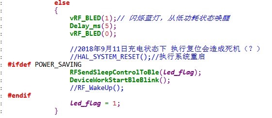
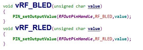
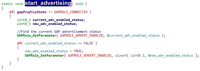
      From the low power state wake-up, there is no application layer processing. This is the original processing in the sdk. What the application layer does is configure a key to trigger the external interrupt. It is described in the SDK document. The external interrupt can wake up the device from the low power state. The configuration of the external interruption of the key and the code of what the system does after waking up by the key and triggering the key by the application layer are as follows:
  • As I read the code and comments you are using standby and not shutdown.

    Why do you use PINCC26XX_WAKEUP_NEGEDGE if you are in standby? Have you tried PINCC26XX_IRQ_BOTHEDGES instead?
  • Original           

    PIN_setConfig (RFInPinHandle, PINCC26XX_BM_WAKEUP, RF_KEY | (PINCC26XX_WAKEUP_POSEDGE));           

    Change to:           

    PIN_setConfig (RFInPinHandle, PINCC26XX_BM_WAKEUP, RF_KEY | (PINCC26XX_IRQ_BOTHEDGES));          

    Is that the change? Or PINCC26XX_BM_WAKEUP needs to be changed, because the header file of pin is defined as follows:


    If PINCC26XX_BM_WAKEUP is not changed, will it affect to use PINCC26XX_IRQ_BOTHEDGES alone?

  • My suggesting is to just use interrupts (following the setup from the pininterrupt example and not any options that are related to shutdown.
  • Okay, I'll revise it like this. The test time is estimated to take about two weeks to give back.thanks!