This thread has been locked.

If you have a related question, please click the "Ask a related question" button in the top right corner. The newly created question will be automatically linked to this question.

sample's timing difference control

Part Number: CC2640R2F

Hi ,

 still regarding the AoA subject.

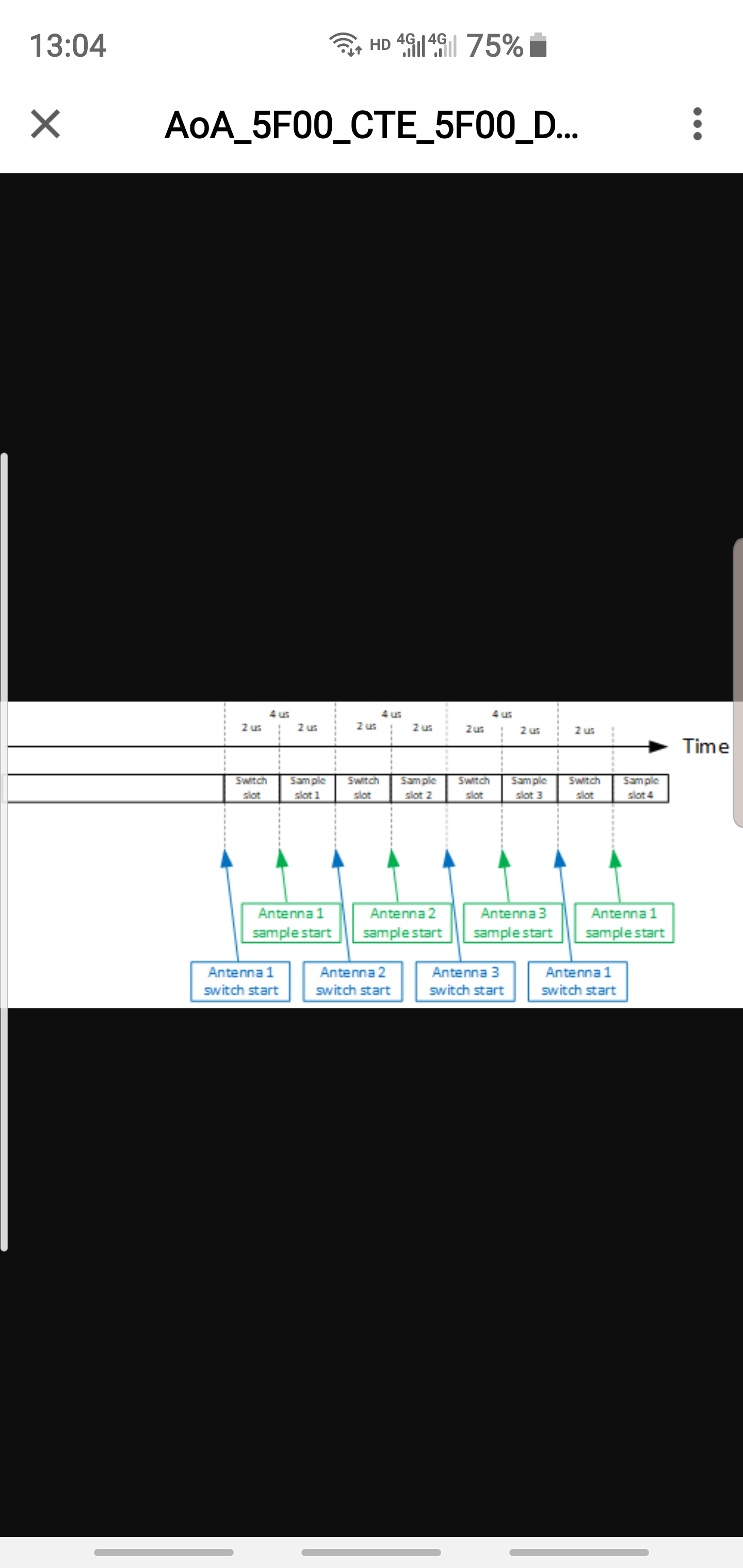
1. accroding this diagram . if the switching time is fixed at 2 us. and 2us for sampling time . base on the 4M S/s. can only sample 4*2 IQs. but accutally we can get 16 IQs per 4us. can you help explain ?

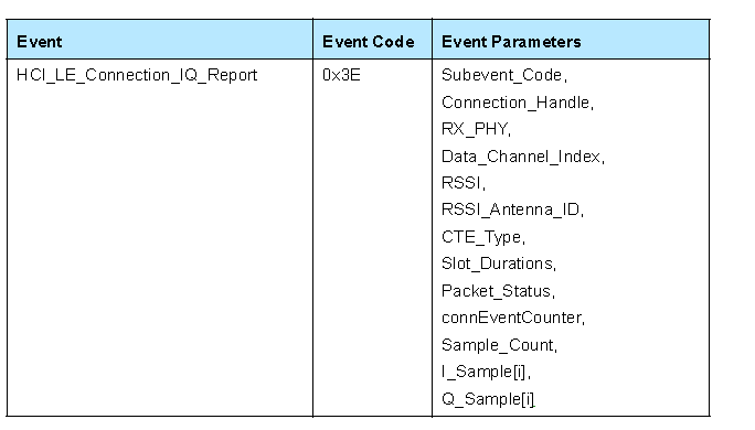
2. how can i open the above function event. so that i can count the timing of each IQ sample【i】?

 pls answer ASAP. i have spend over 2 months on researching this IQ's related to different antenna's phase difference ...no further progress.

thanks

Leison

  • Hi,
    Which SDK version are you using?
  • Hi,

    1. During the 2us switching slot, there are still I/Q samples, but just not usable. There is a section in SimpleLink Academy which covers this. The I/Q sample is continuous and it does not know whether the antenna is switching or not, the application layer has to discard the data during post processing. Even though this is made for 2.40 SDK, but the concept is the same. In our 2.30 SDK, we are not following the BT5.1 spec as it's TI proprietary solution.
    dev.ti.com/.../ble_aoa.html

    In the 2.30 SDK , we have tuned the antenna switching to at the later 2us instead of first 2us, therefore, in our example, you can see that we are using I/Q samples from index 0~7. This is explained in our 2.30 SDK user's guide
    dev.ti.com/.../index.html

    2. If you are looking for BT5.1 like solution, please move to 2.40 SDK. All the needed information can be found in
    dev.ti.com/.../localization-index.html
    dev.ti.com/.../ble_aoa.html
  • Hi,
    Can we make a timestamp for every IQ we captured in every 4 us ? so that we can justify the A1.1 and A1.2 's , A 1.2 and A1.3 's phase difference
    are reasonable calculated and expected ?

    Leison
  • No, the captured is done in the radio core and can't be changed.
    We have already verified it and that's how we got the result shown here:
    dev.ti.com/.../

    Can you tell me how you calculate the phase difference and what your result it?
    Have you read through our documentation yet?
  • Hi christin.

    can i confirm with you  one question?

    1 .we measured thw array anteanna distance is 3.5CM  and use this number to calculate the relations between the phase difference and the angle.

    2. does the IQ NEED additinal filter to match the sine wave?

    3.we always found when the actual angle is more than  40  degrees .the  pahse difference mismatch the phase diff goal  .for example when we tested at 1.5meters away with 50  degree.can only measured and calculated 50 degrees more or less phase diffs.but the phase diff goal is 72  degrees .20 degrees gap.we think a lot ways.but can not know why is the potential reason to compesate this 20 derees

    pls suggest?

    urgent

    leison

  • Hi,

    1. It's stated in the SimpleLink Academy that in our example we did not do the final conversion from relative phase difference to final angle but you can still do it.
    dev.ti.com/.../ble_aoa.html.

    2. No.

    3. What's your environment? For development, I would recommend to start with antenna chamber to remove the interference. And then in that environment your calculated angle should fit the real angle perfectly. Then you can move to open outdoor area and office area to improve your algorithm.
  • Hi

    Chritin,

      we actually tested and collected the IQ datas in the Charmber room. and calculated in the Matlab tools.

    we doudled is was caused by the "sampling process".  when we converted the IQ data to phase related information . we compared each phase degrees for every 4 us. for example: theata A1[0]-A1[1] and Theata A1[1]-A1[2]..... and found each value gap is not matched 22.5 degree. even some times far less 22.5 degree. like 17/18 degree in the first 8 IQs. some times like 28 degrees.  it is means some problem with the sampling process. that is the potential reason that caused the phase diff error. that is why if anyway we want to make timestamps to each IQ.

     Leison

  • Hi,

    Have you taken a look at our Software User's guide?
    It's described here that in reality the 250kHz might not be perfect due to the frequency offset in carrier frequency. So you need to do some compensation even when testing in chambers.
    Please take a look at here:
    dev.ti.com/.../localization-index.html

    Starting from the following paragraph:
    "Something to highlight is that in reality the 250kHz might not be perfect (for example, could be 255kHz or 245kHZ), therefore, there is slightly phase difference between ant_1 sample_n and ant_1 sample_(n + 16*1). ...etc

    The sampling time is fairly accurate or else we won't be able to provide the data shown in the booster pack landing page(dev.ti.com/.../node
  • for sure 。 we checked that may caused 2-3 degree phase diff. we did the compesation for this .but after this .still has 10 degrees gap.

    we know your source code has another 5/10 AoA angles compesations for different Channel ( channel 37/38/39... ),we don't use your source code to calculate the AoA angle . we want to find out where to lead this phase diff loss.

    Leison

  • How did you check it's only 2~3 degree difference? How do you do the frequency offset compensation?
    Can you please provide data(RAW IQ) and detail process of how you calculate the angle?
  • hi christin,

     attached excel file is the detail processing .pls help checked !

    thanks

    Leison

  • angle-cal.xlsx

    attached excel file is the detail data process! pls help checked

    Leison

  • Hi,

    I will need you to add explanation regarding what the data means. I have no idea what each columns are for and how to interpret them
  • sorry to confuse you .here are some remarks for each collumn definitions

    for verification.xlsx

  • Hi,

    Do you have raw data. I want to see I/Q data in the same file as your post process relative phase difference data.
    It's not possible for me to analyze without raw I/Q data.
    If there are raw I/Q data in the excel sheet, can you tell me which columns are I and which columns are Q samples?
  • 8512.for verification.xlsx

    Hi,

     here it is . BTW. Can you let me know the CC2640R2F chip's modulation index ? is it stable modulation index @0.495 and 0.505 or standard modulation index ? if not stable modulation index. can we modify to stable modulation index ?

    Leison

  • The modulation index 0.5. The standard modulation index for BLE.
  • hi.

    standard modulation index of BLEshould be 0.45 and 0.55。The measurement carrier frequency will be 225Khz and 275Khz.

    Leison

  • Hi,

    You are correct, our modulation index is between 0.45 and 0.55. In our aoa application code, we did frequency compensation to account for the variation of modulation index.
    The content can be found here:
    dev.ti.com/.../localization-index.html

    We do not support stable modulation index.

  • Understood! that is why we are alwasys asking the" 250K Carrier wave deviation "!  we are not sure if that is the best way to compesate this deviation. since the application eveirement is different. the antenna board producing process different . even some times in same manufacture site,but for different manufacture date. that maybe cause the antenna's parameter setting up is different . maybe the parameter is different .

     we also found for each version SDK that parameter is slightly different .( i means that antenna confirg file like  sign/gain/offset.....)

    May i ask one question ?

    Can you let your RF engineer to share some key technology to us ?  like upper digital conversation/Down digital converstation algorithm for phase/phase to angle/mix frequencey to IF . if we know your detail method we may have a way or some algrithm to compesate this phase different  .

    thanks

    Leison

  • Hi.
    OK .thanks. that is to prove why always has phase difference deviation according the " angle and phase difference relationship". we are now checking the " 250K carrier wave deviation range". and also to check where is this deviation happen .( like upper digital conversate or Down digital conversate ) . if your team or RF engineer has this kind of RF testing report to share ?
    also what kind of agreement we get. that you can share some RF baseband algorithm to share us ? like " RF mix to IF/integrator algorithm to phase /phase to angle etc regarding the RF baseband process method ?
    we think this is very important step to compesate this "250K wave deviation" that caused the phase different.
    we also found for each different version SDK TI provided ( the parameter setup is slightly different for gain/offset...) suppose that application envirement/mfg process/mfg date change. that may to re-setup the parameter. that is not reality !

    thanks
    Leison
  • Hi,

    Unfortunately, we can't share the information with you.(Can you let your RF engineer to share some key technology to us ? like upper digital conversation/Down digital converstation algorithm for phase/phase to angle/mix frequencey to IF . if we know your detail method we may have a way or some algrithm to compesate this phase different .)

    The reason those values are different are due to the way that the tone is sent at the different place. One is embedded in the adv payload and the other one is the BT5.1 style, CTE.
  • Hi christin,

     Can you send us your calculation method with embedded formular ? thanks

    Leison

  • Hi,

    The calculation can all be found in our embedded software.