Other Parts Discussed in Thread: INA188
Hi all,
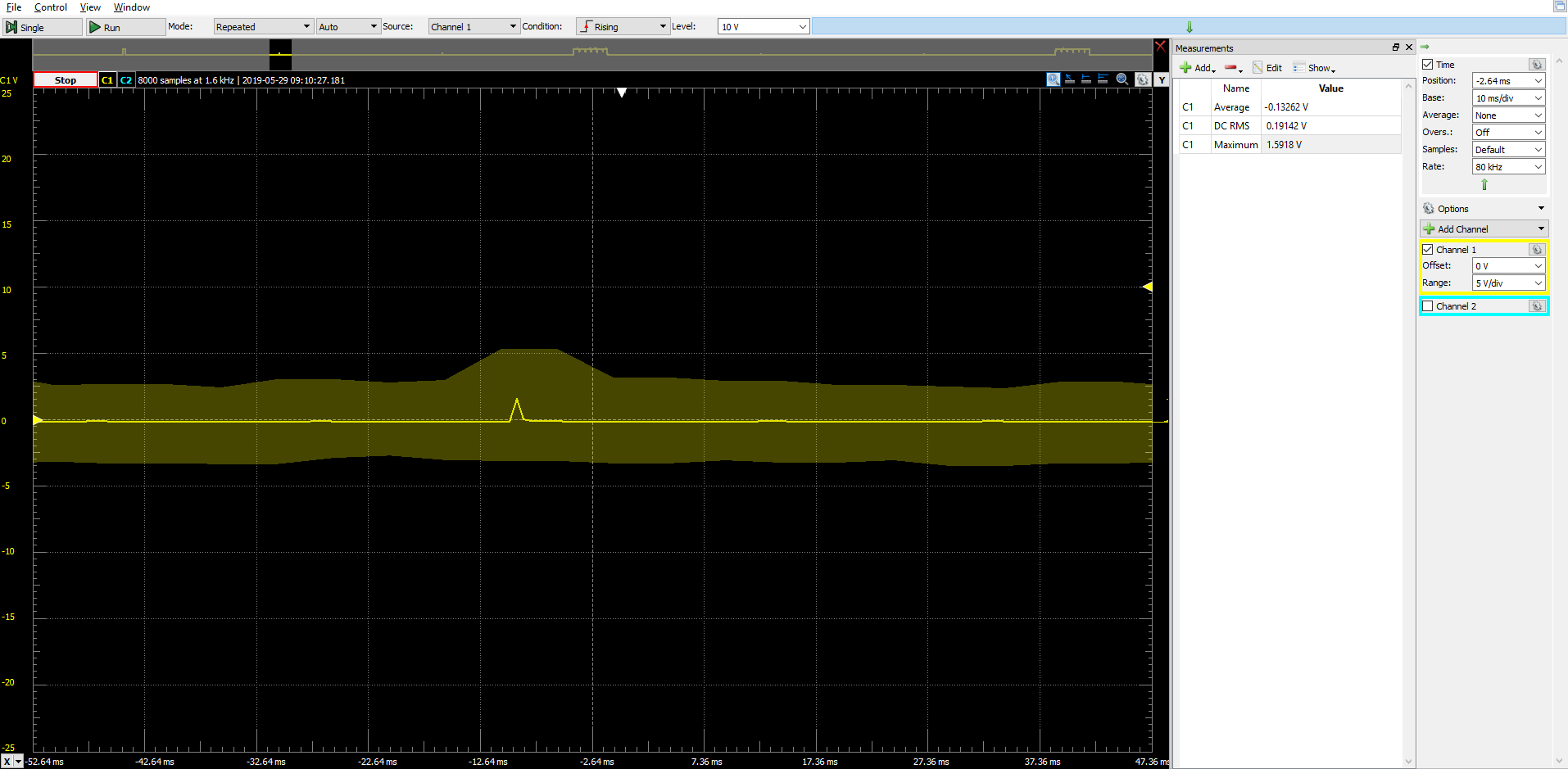
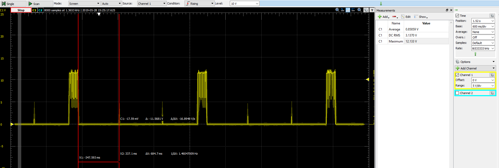
In the picture below, scanning pulse of 150 [ms] is shown (occurring each 2 seconds). Between each scanning pulse, device is entering standby mode (i also proved it with power driver callback events), but current spikes are present (i am not using DC-DC converter configuration and its using is disabled in ccfg.c file) and average sleep current isn't ~ 1 uA as it should be. Also, everything needed is disabled in board configuration file.
Signal shown is gained by factor of 1000 using TI INA188. (followed measuring procedure is from https://e2e.ti.com/support/wireless-connectivity/bluetooth/f/538/t/592223).
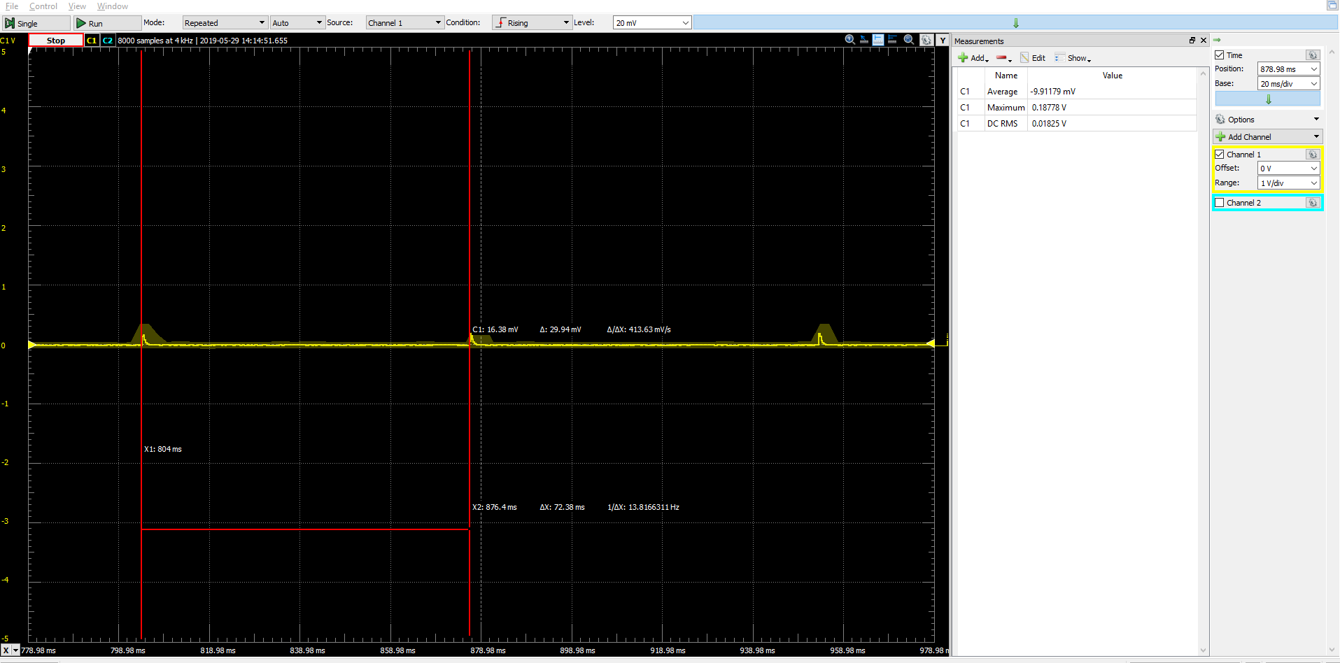
On second picture, period between two scanning impulses is shown (standby = 1.85 s, up to next scheduled scanning). As it can be seen:
DC RMS = 0.0599 V / 1000 = 0.0000599 V = 59.9 uV (which is 59.9 uA, because voltage drop is measured on known 1 ohm resistor)
Max = 2.417 V / 1000 = 0.002417 V = 2.417 mV (which is 2.417 mA), caused by spikes!
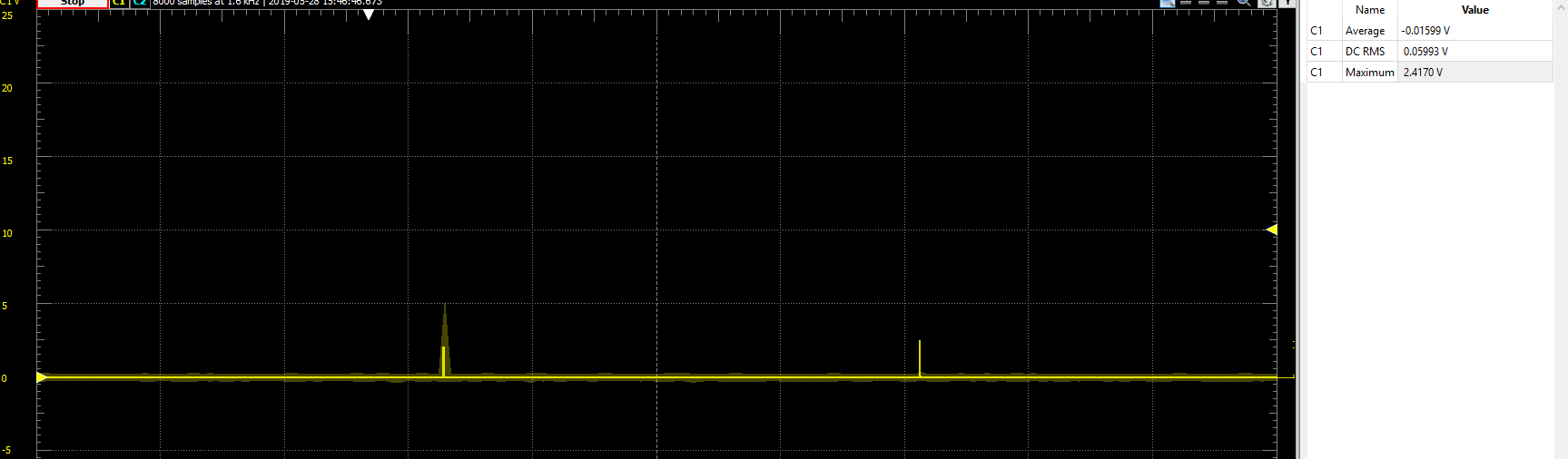
My question here is, what can cause those spikes to occurs?
They look pretty equidistant from scanning pulse, each time.
BR,
Borivoje Tasikj