This thread has been locked.

If you have a related question, please click the "Ask a related question" button in the top right corner. The newly created question will be automatically linked to this question.

CC1352P: BLE Advertisement on a custom board with CC1352P chip

Part Number: CC1352P
Other Parts Discussed in Thread: CC2540, CC2642R

Hello ,


I would like to know if I can run the BLE Simple peripheral code on a custom PCB board designed with the CC1352P chip. Is there additional libraries required or just flashing the chip using a CC1352P launchpad will suffice. 

I'm new to this and any help will be appreciated. 

Thanks

  • I suppose you only need to revise the IO pins in board file according to your own CC1352P custom design to make it work.

  • Hi Sanjay,

    As you state that you are new to this, I would also like to direct you to our user's guide and the topic of custom hardware:

    http://dev.ti.com/tirex/content/simplelink_cc13x2_26x2_sdk_3_20_00_68/docs/ble5stack/ble_user_guide/html/ble-stack-5.x/custom-hardware.html

    This will provide you with more specifics on the board file, and other configurations that might prove useful.

    Best regards,

    Vetle 

  • I did try changing the PINS to make peripherals like LEDs to work.

    I'm not able to make BLE Transmissions and the only difference on my board is that I'm not using the RD Switch , instead I have 2.4GHz from pin 1&2 with the balun connected to an antenna. Basically, instead of the RF Switch Ive got the antenna. attaching pic below for reference. 

    Any help will be appreciated.

  • I was able to pick advertisements on a BLE Sniffer. But I realize the device does not check for scan_req to send any response. 
    I'm sure the advertising mode is connectable scannable legacy advertisement.

    Any suggestions to verify the RX/TX PIN functionality

  • Hi Sanjay,

    The TX functionality can be verified, as you have done, with a sniffer. If you are able to, you can attach a sniffer log. For the RX functionality, it could be useful to have a look at the data you are receiving (if any). In this case, if possible, setting up a serial connection (UART) would help you.

    I assume you have used the technical documents related to the chip: 

    http://www.ti.com/product/CC1352P/technicaldocuments

    And I would recommend that you double check all the HW configurations (RF related) relevant to your custom design (PDF file):

    http://www.ti.com/lit/pdf/swra640  

    Best regards,

    Vetle

  • Hi Sanjay,

    Were you able to get this to work?

    Best regards,

    Vetle

  • Hello Vetle,

    I'm yet to verify the RX part for BLE as I'm still working on TX for BLE and Sub 1GHz. 

    In addition to this I had opened a parallel ticket for Sub 1 GHz, to verify TX/RX using SmartRF Studio, but my custom board failed to function using SmartRF Studio. (attached link for the same :https://e2e.ti.com/support/wireless-connectivity/sub-1-ghz/f/156/t/842978 )

    Could you share some thoughts on that post as well. The issue is , I'm able to verify BLE TX using a BLE Sniffer and when running the simple Peripheral example. But in the case of using SmartRF studio I am not able to perform any TX/RX operations. 


    Correct me if I'm wrong, Since the simple peripheral examples runs and is able to transmit packets there is nothing wrong with the Radio design right?

    Kindly help me out. 

    Thanks

  • Hi Sanjay,

    Thank you for the update.

    I see that the other thread you linked is assigned to another engineer with expertise in the topic you need help with. I would recommend that you continue the discussion in the new thread.

    Have a good day, and good luck!

    Best regards,

    Vetle

  • Hi Sanjay,

    Can you elaborate on what you mean by "not able to perform any TX/RX operations"?

    Regards,
    Fredrik

  • Hello Fredrik,

    Thanks again for reviewing this thread. 

    What I intended to convey is as follows:-

    1) I flashed my custom board with the Simple_peripheral example, the changes I made to advertising parameters are as follows:-

    Advertisement type : Connectable & Scannable
    Advertising interval: 500ms
    Advertising channel: primary (channel 38)

    2) I was able to verify the advertisements a sniffer tool using CC2540 dongle, but I couldn't capture the advertisements on the Ti simplelink starter phone app.

    The same example when using a launchpad, shows up as "Simple peripheral" on the App, this is the scan response data packet.

    3) It seems like the board cannot capture any scan request packets in order to send a scan response packet.
    Since the advertisements are of the connectable & scannable type, the custom board should be able to listen to scan request packets right?

    My goal here was to verify that the BLE Radio is functional in order to make transmissions and receptions of packets. I'm able to verify TX but not RX. 

    Kindly help me out. 

    Thanks

  • Hi Sanjay,

    As discussed in the other thread, this could be caused by a carrier frequency offset. Can you verify the frequency accuracy of your board and if required tune according to this application note:  www.ti.com/lit/pdf/swra640

    Regards,
    Fredrik

  • Thank you Fredrik, 


    I'll verify this and will update you with the spectrum analyzer results.

  • Hello Fredrik, 

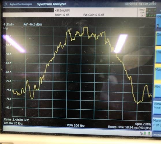
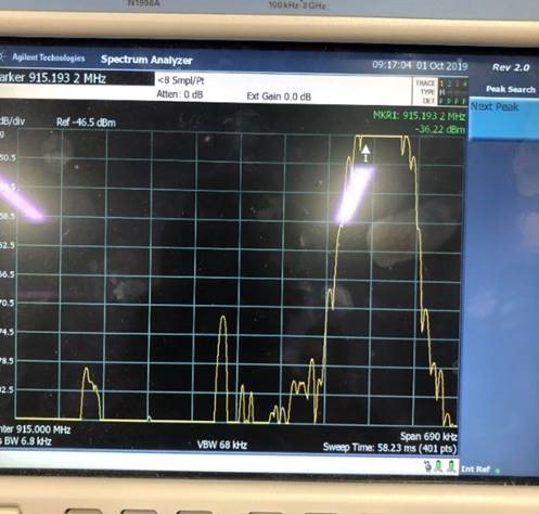
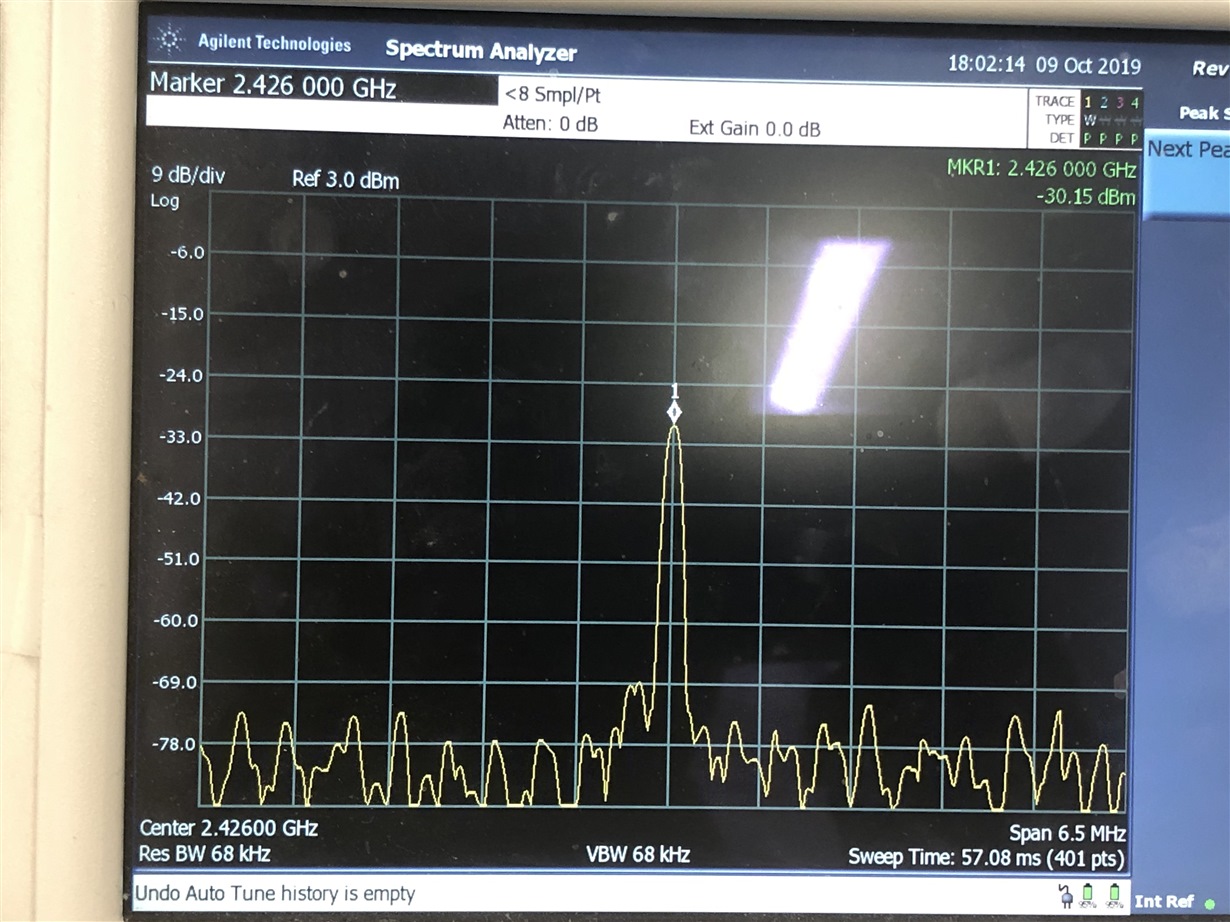
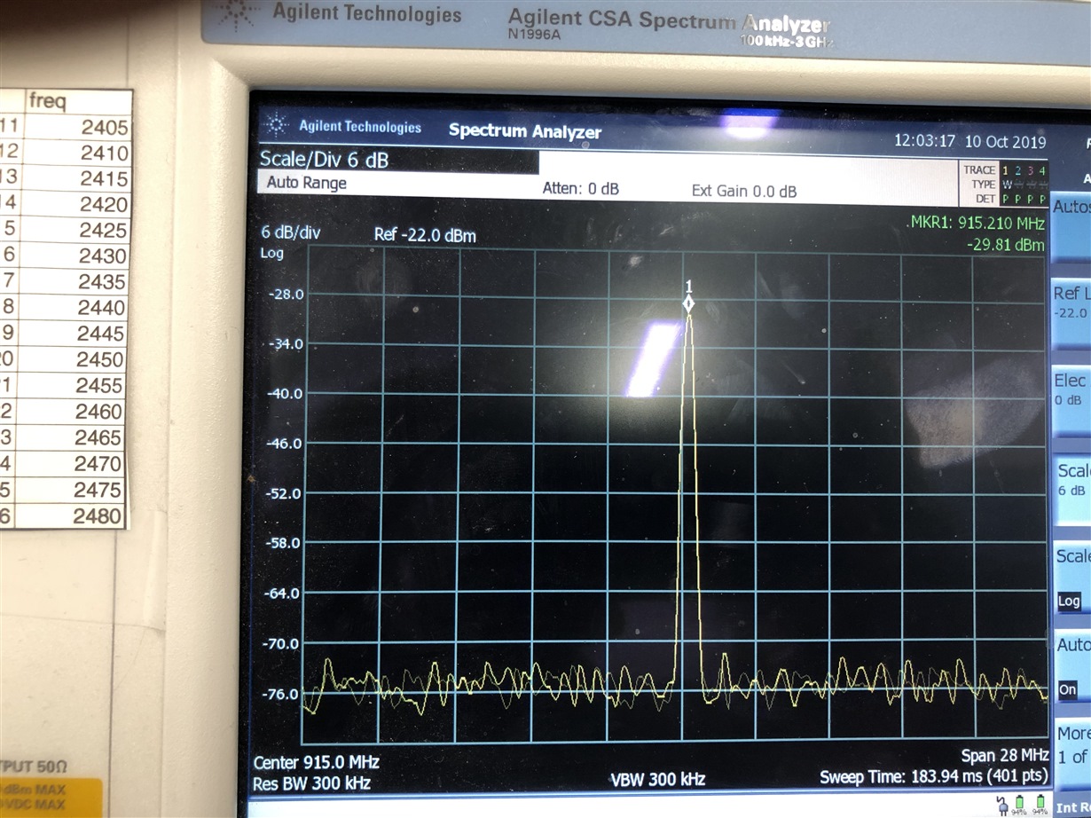
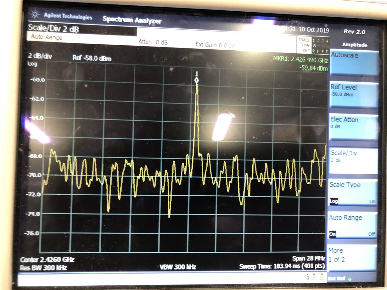
    I'm attaching the spectrum analyzer results below:-

    FOR BLE , its centered at 2.426GHz

    In the case of Sub 1GHz, its centered at 915MHz

    From the spectrum analyzer results, it doesn't seem like there is a frequency offset,. Any other suggestions that I can look into Fredrik?

    Kindly help me out.

    Thanks

  • Attached Sub 1GHz results:-

  • Hi Sanjay,

    You need to measure using a unmodulated signal so you look at the carrier only. You also need to turn down the input gain so you can see the peak of your signal.

    Regards,
    Fredrik

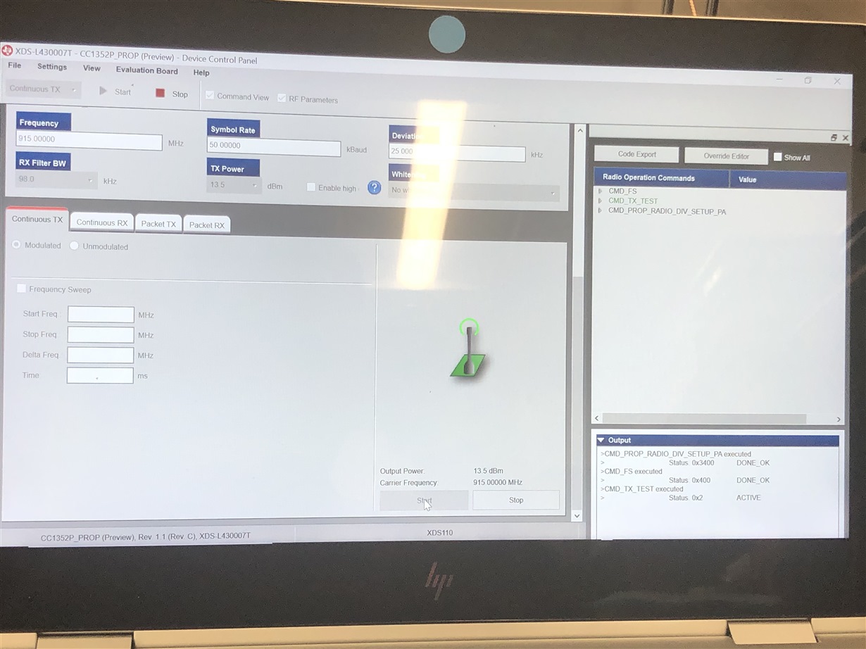
  • I used Smart RF Studio to make CW Transmissions.

    1) Attached below are the results from a CC1352P Launchpad.

    Sub 1 GHz:-

    BLE

    I could also see the test status showing ACTIVE in both cases

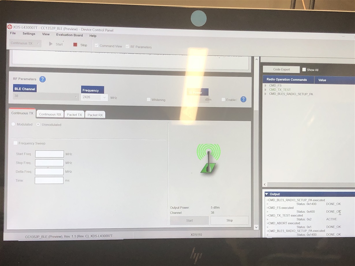
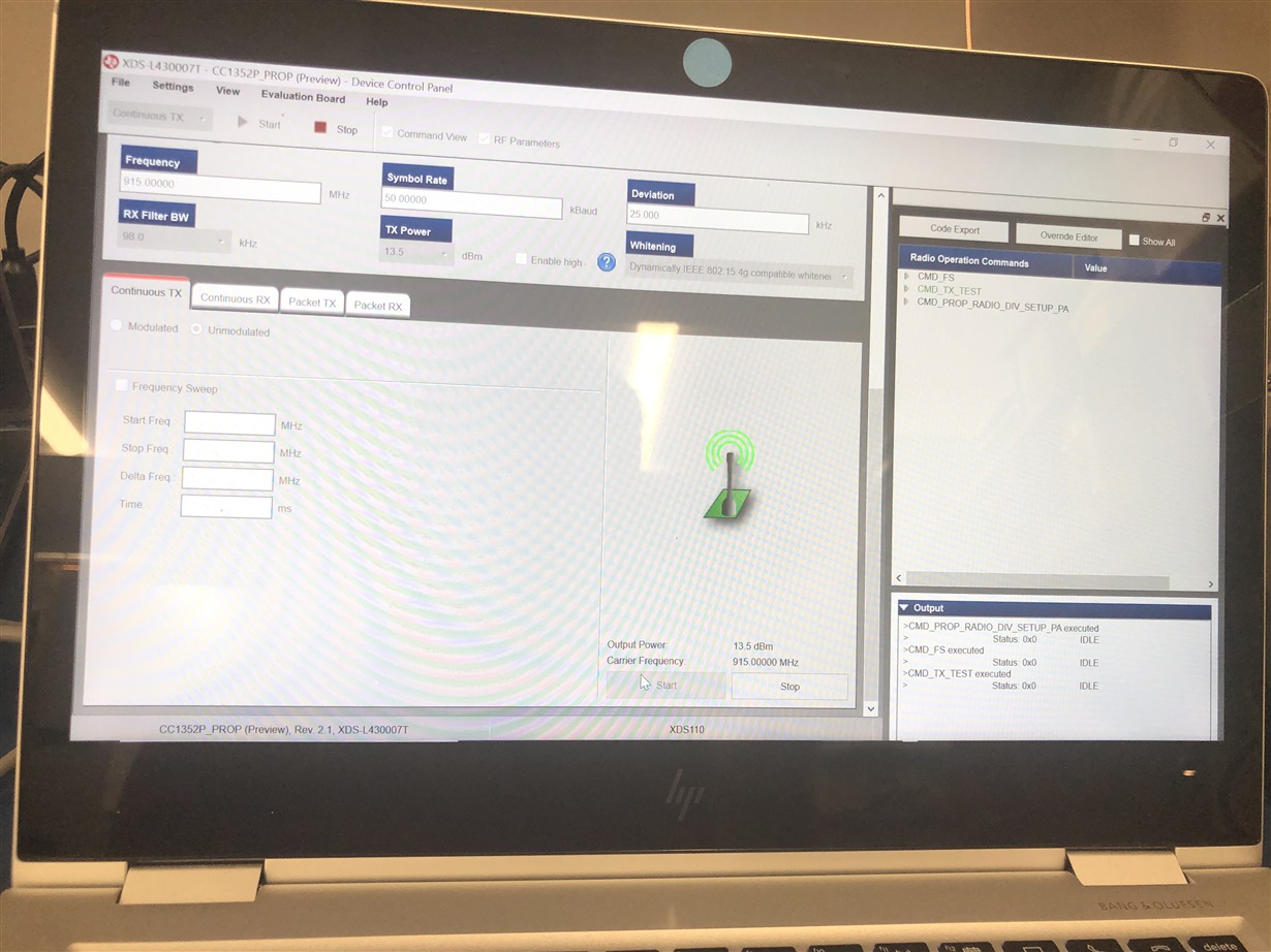
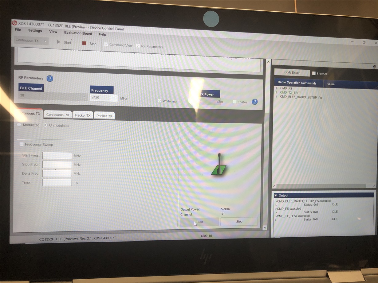
    2) ON interfacing the Chip on the Custom board using JTAG connected to the XDS 110 OUT pins of the launchpad with jumper pins disconnected,  to use with Smart RF Studio there was no Transmissions seen.

    The status on the Smart RF Studio shows Status INACTIVE

    Sub 1 GHZ

    BLE

  • Hi Sanjay,

    That looks like an old version of SmartRF Studio. Can you try the latest version? 

    Regards,
    Fredrik

  • Hello Fredrik,

    Thanks for the help .  An update to the SmartRF Studio solved the issue.  I was able to use Smart RF Studio as Continuous Tx and Continuous  RX to verify feasibility of my board for both BLE  & Sub 1 GHz.

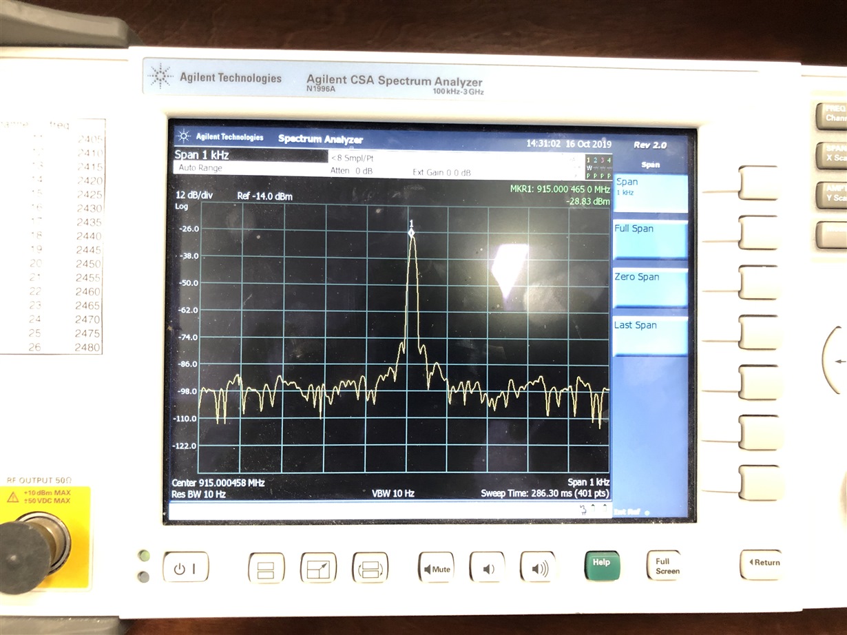
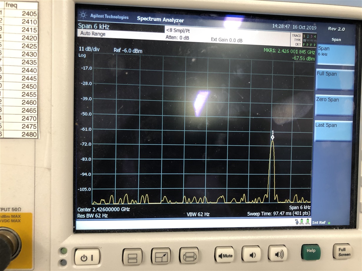
    Spectrum Analyzer results attached below:-

    However, I was trying to do a packet TX/RX operation and I had difficulty in receiving packets being transmitted using Smart RF studio . Any suggestions here to fix this ?

    And one of the Launchpads that was working earlier with the older version of SmartRF Studio shows the below error now:-

    Kindly help me out, and I apologise for the delayed response.

    Thanks

  • Hi Sanjay,

    You should reduce the frequency span on the spectrum analyzer to confirm, but it looks like you have a frequency offset of 200 ppm. This is very large and explains why you are not able to communicate with you board. 

    You need to configure the load capacitance for the crystal as described in this application note: www.ti.com/lit/pdf/swra640

    The LaunchPad that does not work with latest SmartRF Studio is probably using the engineering version of the IC which is no longer supported.

    Regards,
    Fredrik

  • Hello Fredrik,

    Thank you for your patience.

    You're right with the cap-array tuning. The default that showed up for the CC1352P was around -43, and as per the document the default is around 6.7pF.  I just wanted to confirm with you if the default value will be '0' which is 6.7pF or -43 as seen in Smart RF studio. 

    I did look into the same for a CC2642R and the default calue is '0' which is 6.7pF. 

    In addition , I was able able to verify packet TX/RX too. 

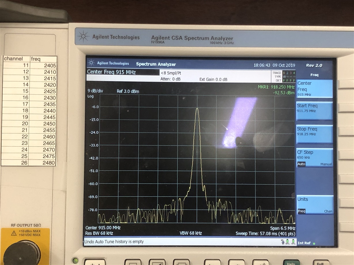
    Below are the snapshots of the spectrum analyzer for continuous TX , where Sub 1GHZ is at 915 MHz and BLE is at (channel 38) 2.426 GHz
    . I did reduce the span too. 


  • Hi Sanjay,

    That looks a lot better!

    The default value for CC1352P is actually -43 which means that the cap-array is disabled. This is true both in SmartRF Studio and in the SW examples. The reason is due to what is explained in footnote 3 in the 48 MHz crystal oscillator section in the datasheet as well as advisory Radio_01 in the errata. The CC1352P LaunchPads do thus come with external load capacitors mounted. 

    For you custom HW, you can use the internal cap-array if the errata advisory is not a concern for your application, but in that case you have to enable the cap-array as you did in SmartRF Studio also in CCFG.c.

    Regards,
    Fredrik


  • Thank you very much Fredrik,

    Please correct me if I'm wrong, Only in the case of using +20dBm power amplifier, there is a possibility of spurious emissions in the factor of N* 48MHz, right ?

    I had copied the older design of the launchpad, without the external capacitors on the 48MHz crystal.

    Currently, I am not using the PA and I just wanted to know if you suggest using the internal Cap-array until I make the next  update to my custom board ?

    I really appreciate the help .

  • Hi Sanjay,

    Yes, it is only in the case of using the 20 dBm PA a risk for spurious emission which may affect the regulations listed in the errata. It is otherwise perfectly fine to use the device, PA included, with internal cap-array. 

    Regards,
    Fredrik

  • Thanks a lot for all the suggestions Fredrik .