This thread has been locked.

If you have a related question, please click the "Ask a related question" button in the top right corner. The newly created question will be automatically linked to this question.

TRF7964A: FIFO is empty even if RX completes successfully

Part Number: TRF7964A
Other Parts Discussed in Thread: TRF7970A

Hi,

we seem to have a similar problem as the original author of the linked discussion, albeit with a slightly different IC.

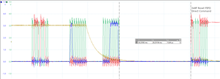
An ISO15693 command sequence completes successfully with Irq_srx interrupt, but the following query of the FIFO status register yields zero bytes to be read. The problem persists for any subsequent commands.

Just as described in the related thread, not all of our PCBs show this behaviour but we see a failure rate of about 30 %. This problem can be reproduced and resolved by powercycling the IC.

We have tried every trick in the book to avoid this issue by means of configuration changes, reinitialization and application of generous wait states in all imaginable places but nothing seems to be working so far.

The original discussion unfortunately does not present an explanation or a solution to this problem and we're still curious whether this issue can somehow be resolved.

  • Hi,

    the thread you referred to is very old and I don't how it was resolved. In the meantime I am not aware of a similar problem.

    Can you please give more information about your system. Which interface is used, SPI with SS ? Which MCU and firmware? Is the firmware based on one of our examples?

    If available, a trace of the SPI communication with timing information could be helpful.

    Best Regards,

    Helfried

  • Hello Helfried,

    thank you for the reply. I have attached a PDF file with a couple of SPI traces detailing our problem.

    We're using SPI with SS at 2 MHz clock speed. I have tried increasing and decreasing the SPI clock speed (1 MHz for the attached traces) but to no avail, the problem still persists. The MCU firmware is fully custom and not based on any of the examples unfortunately. There are only very few deviations from the default (POR) TRF7964A configuration though:

    • SYS_CLK Control Register -> 0x11 (13.56-MHz crystal)
    • Interrupt Mask Register -> 0x1E (Disable FIFO watermark interrupts, irrelevant for our use case)

    Those registers are written at the end of the TRF7964A initialization sequence in compliance with the instructions in the data sheet (p. 45).

    Please let me know if you have any suggestions or if you need any more information.

    TRF7964a.pdf

  • Hi,

    as far as I can see from the timings you have supplied, it looks ok for me and this part seems to be ok.

    What happens between the TX start IRQ and the RX end IRQ? Was the FIFO cleared with direct command 0x0F as described in the FAQ chapter 4.6?

    https://www.ti.com/lit/sloa246

    If not already available here the link to the document "Firmware Design Hints":

    https://www.ti.com/lit/sloa159

    Even it says TRF7970A, this document is also valid for the TRF7964A.

    Best Regards,

    Helfried

  • Hi,

    thanks for all your suggestions. The FIFO reset direct command is sent about 15 us after the IRQ status register has been read (see attached image). I could not find any information regarding timing constraints but the RX IRQ is usually asserted only 4 ms after reading the IRQ status register (for an Inventory command anyway), so I thought this was safe.

    Section 7.2 and 7.7 of sloa158 have something to say about SPI with SS that caught my attention though:

    "If a direct command is the last operation in the SPI communication, the SS pins goes high. An additional
    clock pulse must be sent after this happens." and "All direct Command functions need to have an additional DATA_CLK cycle before Slave Select l line goes high."

    This is obviously the case for e.g. the Reset FIFO command. I was wondering whether this applies to the TRF7964a as well. And if so, whether an additional clock cycle is needed before or after CS goes high. I have tried a "dummy write" after the the direct command byte since a single additional clock cycle is somewhat difficult to achieve with our SPI interface. This it seems does not change anything though, for better or worse.

    Section 7.5 in the same document mentions an SPI clock polarity change is needed for FIFO read operations. Correct me if I'm wrong but this does not seem to be the case for the TRF7964a. We would see 'some' data in the traces, it just would not be sampled properly.

    I think all the other design hints and errata have been observed in our code if applicable.

    Cheers

    Björn

  • Hello Bjoern,

    you are right the SPI clock polarity change is not required for the TRF7964A.

    I found the following old E2E thread, saying timing during TRF7970A initialization may cause similar issues as you have reported:

    https://e2e.ti.com/support/wireless-connectivity/other-wireless-group/other-wireless/f/other-wireless-technologies-forum/753240/trf7970a-trf7970a-reading-0-bytes-from-fifo

    Maybe this is something you can check...

    Best regards,

    Andreas.

  • Hi Andreas,

    thanks a lot for digging up that thread. I reexamined our initialization routine but the SoftwareInitialization and Idle commands are only a couple of microseconds apart, followed by a generous 5 ms delay before configuration is done. Followed by another generous 15 ms delay before any commands are being sent. However, I tried turning the separate SPI transactions for the two direct initialization commands into one. Unfortunately this didn't change anything, I can still make the RFID reader 'freeze', for lack of a better word. And no amount of (re)initialization can make it work again, it needs a powercycle to do that. With quite an extended off-time too (in the range of seconds).

    Cheers

    Björn

  • Doing a little thread bump here.

    In the meantime we have done a couple of hardware modifications, mostly related to chip power supply and enable signal handling. Things we thought might cause any problems for one reason or another. None of that lead us anywhere unfortunately and we're still struggling to get rid of this problem.

    So right now we're wondering whether TI offer support in terms of circuit diagram- and/or software review. If this is not the right place for such a request we would be thankful for being referred to the appropriate contact.

    Cheers

    Björn

  • Hello Björn,

    I can review your schematics and software if you want, but I can not guarantee that I can solve the problem.

    Best regards,

    Andreas.

  • Hello Björn,

    as discussed in the private chat, it is necessary to initialize the the NFC Target Detection Level register (0x18) with the value of 0x00, to avoid this device misbehavior of 0 bytes in the FIFO Status Register(0x1C) after the RX complete interrupt. This bug and its solution is documented in item "Device#B08" of the TRF7970A Silicon Errata (www.ti.com/.../SLOZ011) and in chapter 6.11 step 7 of the TRF7970A datasheet (www.ti.com/.../trf7970a). Since this information is missing in the TRF7964A documents, I will request a corresponding update.

    Best regards,
    Andreas.