Other Parts Discussed in Thread: MSP-EXP430G2ET, DLP-7970ABP, , MSP-FET
Tool/software:
Hi everyone,
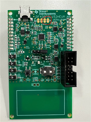
My lab partner and I are working on the RF430FRL152HEVM evaluation board and are encountering some issues. Initially, we tried connecting the board to the GUI using the MSP-EXP430G2ET + DLP-7970ABP setup, but we couldn’t get it to connect.
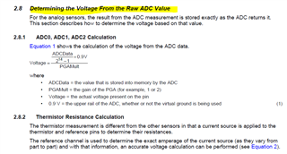
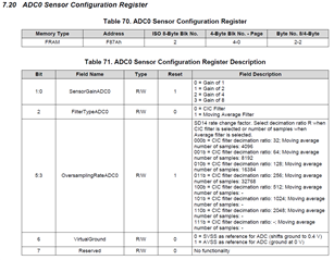
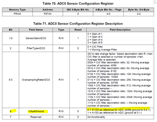
I wrote an iOS app to read and write data to the board and power the sensor chain. The app is getting data from the light sensor (ADC0), and we can see it changing to 0 when we cover the sensor. However, the voltage readings don’t match what we measure on the board with a multimeter. The multimeter shows 0.65V for ADC0, but the raw ADC values are 0x3FFF and 0x2080 which convert to 0.45V and 0.228V using a gain of 2. Adjusting the sensor configuration gain (tried 1 and 2) didn’t change the raw ADC values, though gain is part of the conversion formula. I have tested my app, and I'm sure the issue isn't on my end.
Setup for blocks 0–8:
Block 0: 0x0100040208010000
Block 1: 0x0000000000000000
Block 2: 0x0909090900000000
Block 3: 0x000000000000FFFF
Block 4: 0x0000FFFF0000FFFF
Block 5: 0x0000FFFF0000FFFF
Block 6: 0x0000FFFF0000FFFF
Block 7: 0x00000000000000FF
Block 8: 0xF80100000000A6A3
Results:
ADC0 enabled
Block 9: FF3F802080208020
Block 10: 8020802080208020
ADC1 enabled
Block 9: 0000000000000000
Block 10: 0000000000000000
ADC2 enabled
Block 9: 0000000000000000
Block 10: 0000000000000000
I read in the manual that the firmware might need updating. I tried loading all three firmware versions from slac691.zip onto the board, but I’m seeing the same results with each one. After this when I start sampling, I get a sampling error indicated by the status register (Block 0: 0x000B040004000000). Sampled data in blocks 9 and above read as 0xFFFFFFFFFFFFFFFF.
Any help would be appreciated.
Thanks,
Aditya


