This thread has been locked.

If you have a related question, please click the "Ask a related question" button in the top right corner. The newly created question will be automatically linked to this question.

Failed to debug RF430FRL152H Sensor Patch

Other Parts Discussed in Thread: RF430FRL152H, MSP-FET, TRF7960A, RF430FRL152HEVM

Hello community,

I 'm starting to work on RF430FRL152H Sensor Patch. Our need is to modify  example code NFC_only  by adding functionnality.

Here is my setup:

  • The Patch is supplied with 1.5Vdc source on VDDB
  • JTAG signals TDI, TDO, TMS, TCK, RST are connected to MSP-FET430UIF with VDDsense pin connected to 1.8Vdc (because unfortunatelly the MSP-FET can't work with lower voltage for internal level shifting)
  • CCS V6.1.1 up to date
  • NFC_only Firmware example code

My problem is:

After a successfull compilation, I tried to debug firmware and I get the following error message:

   " Error connecting to the target: unknown device"


I spend lot of time to find what's happenning, I don't succeded to.
If some one can help me to solve, it would be nice.

Thanks all for your support.

Regards

  • If you power the device on VDDB you will have to either in your code or over RF close the battery switch.  The battery switch connects VDDB to VDDSW, which powers the entire device.  If you want to skip the extra work you can simply directly power the RF430FRL15xH by VDDSW pin.

  • Hi,


    thanks Alexander for your answer.

    I try to supply the Sensor directly on VDDSW pin (1.5Vdc) but unfortunately the result is the same.


    You said a way is to close the switch in my code: I can't because due to this issue I can't program the chip with a new firmware which would close the switch.

    The second way is over RF, OK. I have a TRF7960A: Can you explain me, please, the process to do this?


    Or any other idea?

    I have a look in the chip user guide and there are chapters talks about JTAG_ENABLE_ACCESS_PASS_WORD, and another register to control supply.. Is this a way to solve my problem?

    Thanks for your support.

    Regards

  • Couple of things:
    1. Make sure that you have ground connected between the debugger and the patch.
    2. Can you test if your project is able to program a RF430FRL152HEVM?
    3. Does the patch respond to RF commands like inventory? (The chip is loaded with code to respond to ISO15693 commands from the factory).
    4. If the patch does not work with powering by VDDSW pin it is pointless to try to close the battery switch.

    Yes the JTAG enable access password may be of help however please confirm RF functionality is working first.
  • Hi Alexander,

    1. Yes, GND connection between Patch and debugger is OK

    2. I don't have RF430FRL152HEVM, I have sensor patches and a TRF7960A only

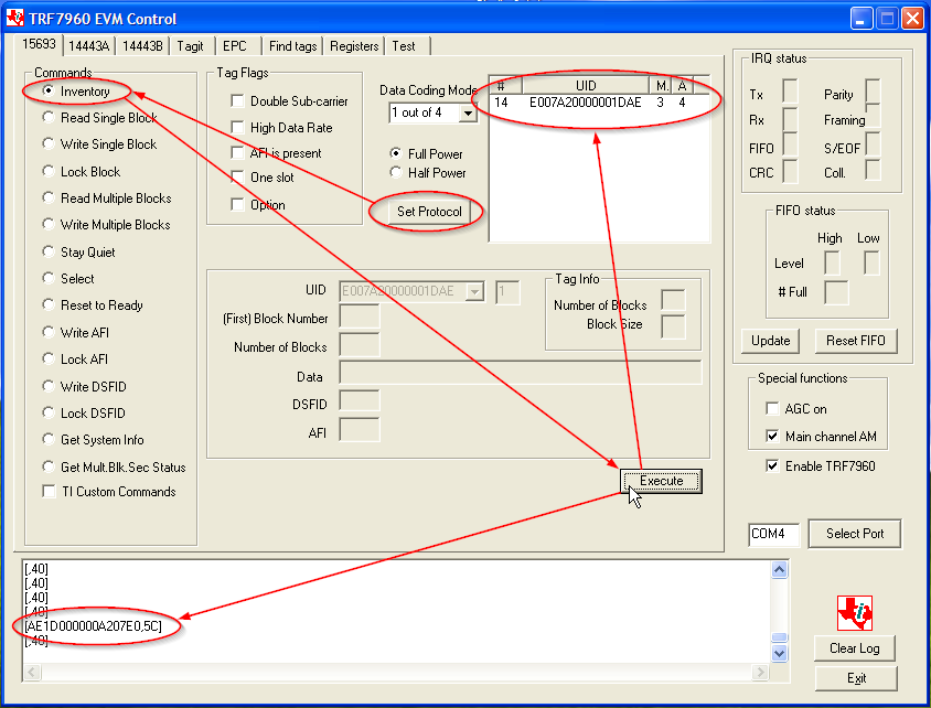
    3. Yes the patch seems to respond to RF commands (see attached picture)

    4. Yes I agree with you.

    What's happening with my setup?

    Thanks for your support

    Regards

  • Couple of other things:

    1. Please double check the rest of your connections to the MSP-FET.

    2. What sensor patch are you using, is it your own developed one or did you get it from TI?

    3. I am supplying on how to cause the internal ROM code to enable JTAG functionality.  Generally this is not needed, but it may help.

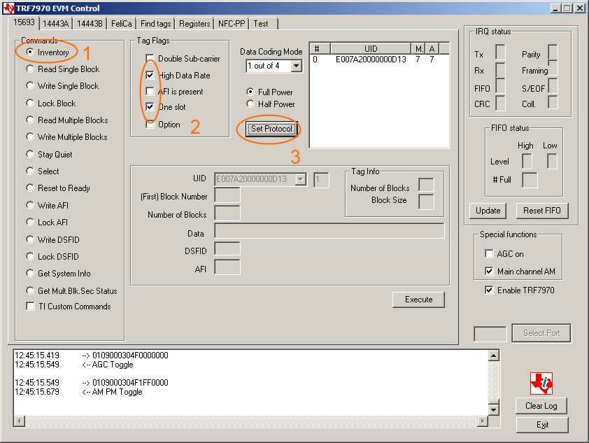
    3a. Click on Inventory.

    3b. Click on High Data Rate

    3c. Clicking on One Slot is optional.

    3d. Click on Set Protocol.

    3e.  Do NOT click on Execute.

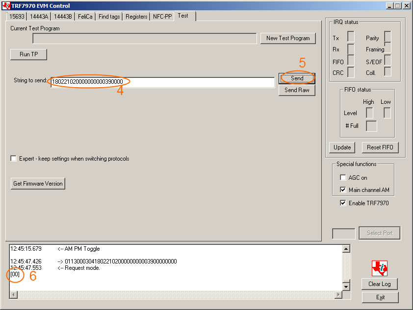
    3f. Enter this text in the text box: 180221020000000000390000

    3g. Click on Send.

    3h.  This should result in a [00] on the bottom text box.

    What this command did is it wrote block 2 with all zeros except on the 5th bit 0x39.  This is the JTAG Enable Password register.

    On reset this register is checked and if it is 0x39 JTAG functionality is configured for the JTAG pins.

  • Hi Alexander, thanks for your help.

    Please find responses to your questions:

    1. Check Passed, all signals are well connected.

    2. I tried 2 patches from TI

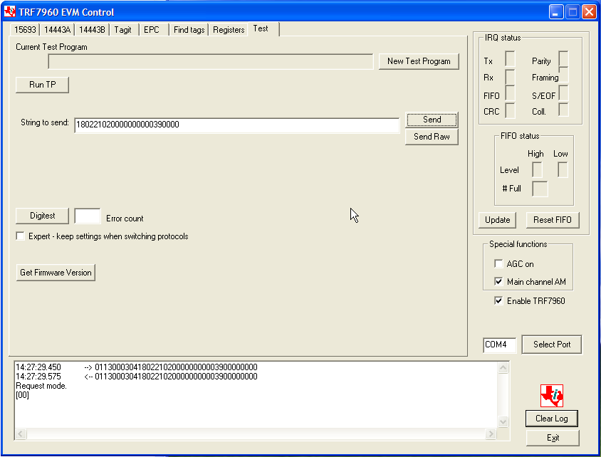
    3. This section has been excecuted :

       RESULT: I get [00] as you expect:

    Here is the screen obtained with one of the patch. It seems to be OK?

    Regards.

  • Okay so the above action was intended to enable JTAG, have you tried to connect with JTAG again to the patch?
    Also if this does not work, after a debugging attempt, maybe you could measure one of the JTAG signals with voltage on it and make sure that it is 1.8V.
  • High Alexander,

    thanks for your answer.

    I try to debug the firmware with no succes.

    Here is one screen capture of JTAG signals TMS, TCK, TDI and TDO. The voltage level is correct. Me be something wrong on TDO: poor rise time?

    According to me, the signal on TDO is not correct due to rise time. Is pull up missing on TDO?

    Regards.

  • Could you please reply with the JTAG pins to RF430FRL152H pin numbers that you are making the connections with? I would like to make sure that we have no misunderstanding.
  • Hi Alexander,

    Here is my setup:

    RF430FRL152H pin3 ->1.5Vdc (to supply the patch)
    RF430FRL152H pin19 -> MSP-FET pin 5
    RF430FRL152H pin20 -> MSP-FET pin 1
    RF430FRL152H pin21 -> MSP-FET pin 3
    RF430FRL152H pin22 -> MSP-FET pin 7
    RF430FRL152H pin10 -> MSP-FET pin 11
    RF430FRL152H GND -> MSP-FET pin 9 (capacitor to ground removed)
    MSP-FET pin 4 -> 1.8Vdc (for JTAG level shifting)

    Thanks for your help.

    Regards
  • I have setup the connections as you did, except for these two changes (they don't seem to be necessary) but the result worked.  Also even though you are supplying the RF430FRL15xH with 1.5V by driving the JTAG lines with 1.8V you are backpowering the device by 1.8V.  As you can see in your scope screen shot the RF430FRL152H is transmitting at 1.8V.  These were the changes:

    1.RF430FRL152H pin 3 to MSP-FET pin 2

    2. MSP-FET pin 4 disconnected.

    Instead of the 1.8V sense I made this CCS setting.  But please first a warning: the maximum voltage that is spec'ed for the RF430FRL15xH is 1.65V.  So 1.8V exceeds this.  It is unknown how many times the device will be able to withstand this higher voltage but in theory it could fail.

    Then I did a disconnected programming attempt for the 1.8V to take effect.  After it failed I connected the MSP-FET to the patch and was able to program successfully.

    There is an alternative: you could program the patch over the RF interface.  However this would prevent any debugging capabilities.  I am supplying a over the air programming executable and also instructions on how to use it.

    /cfs-file/__key/communityserver-discussions-components-files/667/RF430FRL15xH_5F00_OverAirProgrammer.zip

  • Hi Alexander,

    I think something is wrong in my projet:
    I try with the original sample firmware NFC ONLY both in the sensor path and in an EVM module.
    For these 2 HW, the debug launch started as excepected and I can program the chip and debug software.

    So there is an issue in my firmware.
    Regards