This thread has been locked.

If you have a related question, please click the "Ask a related question" button in the top right corner. The newly created question will be automatically linked to this question.

TRF7960A: ISO1443A sequence problem

Part Number: TRF7960A
Other Parts Discussed in Thread: TRF7970A, LM3S6965

Hello,


we are using TRF7960A since many years for ISO15693 transponder.
I try to implement the ISO1443A sequence in our project using your example sloc251.
Please find attached a dvdat file with the SPI communication between our microcontroler and TRF7960A.
There are 4 cycles recorded.
After the pollcmd I get TX and RX interrupt and can read the correct ATQA.
I get an answer to the anticollisioncmd. TX and RX interrupt and can read the first 3 UID bytes.
"88 88 88 16 38 04 A2" Byte 4-6 are the first 3 bytes of the UID, and the 7th byte is the checksum from byte 2-6.
(Transponder ID: 16:38:04:BD:90:7D:3D , ATQA: 0x41 , SAK: 0x20)
My problem is, that I do not get any answer from the sendselectcmd. No TX and RX interrupt.

Best regards,
Michael

INVENTORY_ISO14443A.zip

  • Hello Michael,

    SLOC251 is rather outdated and not a robust implementation.

    I would recommend instead referencing SLOC297: https://www.ti.com/lit/zip/sloc297

    That firmware supports both TRF7970A and TRF7960A.

    I'm not familiar with the DVDAT format, how do I view the trace?

    If you want a full working example, then I can provide a capture that shows anticollision + data read.

    If you do not get a TX interrupt though, I think you have an issue with your command to actually output the data over RF. That would be the only reason for not getting a TX interrupt.

  • Hello Ralph,

    it would be helpful if you can provide captures that shows anticollision + data read.

    DVDAT Format is the Output file from a tech-tools logic analyzer.

    www.tech-tools.com/logic-analyzer-downloads.htm

    Best regards,

    Michael

  • Hello Michael,

    I viewed your logic capture and it looks like you did not change the clock polarity back for your write to the device. So the device is not recognizing your command.

    You should make generalized SPI read and write APIs so the polarity swap is always set correctly.

    Here is a logic capture for ISO14443A read blocks of a Type 2 tag on a TRF7960A: https://e2e.ti.com/cfs-file/__key/communityserver-discussions-components-files/667/3288.Type2_5F00_Read_5F00_Blocks_5F00_New.logicdata

    You can view it with the Logic software from Saleae: https://www.saleae.com/downloads/

  • Hello Ralph,

    I use the same SPI send function for the commands. I asume that the swap of the polarity should be ok.

    selectTag              {0x8F, 0x90, 0x3D, 0x00, 0x0F, 0x26}; and

    anticollision CMD {0x8F, 0x90, 0x3D, 0x20, 0x93, 0x20}; are working

    I am able to read the first 3 Bytes of the UID (16:38:04:78:7C:7D:3D), but I do not receive any answer to the

    select cmd            {0x8F, 0x91, 0x3D, 0x00, 0x70, 0x93, 0x70, 0x88, 0x16, 0x38, 0x04, 0xA2};

    Have you any other idea?

    Bes regards,

    Michael

  • Hello Michael,

    I re-checked your capture you are right, you do have the polarity swap handled correctly. Sorry that I misevaluated that.

    Comparing your capture to my own again and closer... the only thing I can think is that you don't have a 0x8F to clear the FIFO after RX. I am aware the command for TX does the 0x8F, but in all our software, we do a standalone 0x8F after reading the FIFO, and then start the TX chain with the 0x8F followed by the rest.

    Try adding that and see if that solves it.

    Beyond that, I didn't see anything else different.

  • Hello Ralph,

    I added the clear FIFO cmd after RX, but it solves not the problem.
    You capture seems to be for TRF7970A. Can you provide a captue for TRF7960A?
    I tried all register settings from your captue and your TI examples, but it is always stay at the same problem.
    Please take another look to my new caypture is you can see any error.
    I don't know how to go on.
    Can I read any register to get an error code?
    Can you reach you by phone?

    Best regards
    MichaelINVENTORY_ISO14443A_2.zip

  • Hello Michael,

    I will see about getting you a correct capture tomorrow, I thought that I had one for TRF7960A but apparently not.

    Error codes would be from IRQ Status.

    Once I have the new capture I'll compare it directly to your own and see what else I can spot.

  • Hello Michael,

    I am not sure why there is still the missing IRQ for the TX Complete. Can you have a check after 1 millisecond passed to read the IRQ status register to see if any flags are set?

    Also it looks like you write to registers 0x14 and 0x18 but those don't exist on the TRF7960A. Doubtful that is an issue but I'd remove those.

    Here the full capture for the TRF7960A: https://e2e.ti.com/cfs-file/__key/communityserver-discussions-components-files/667/TRF7960A_5F00_Type2_5F00_Read_5F00_Blocks.logicdata

    Also, looking between the waveforms I noticed that you have a very long delay from when you get the response to your 0x93 0x20 and when send the response, 4 ms or so, compared to our example which has sub 1 ms delays between commands and does the whole process in 5 ms.

    That said, I tried introducing delays and tested with NTAG 213 and it still worked. I am not sure what tags you use, but low chance that maybe the tag is timing out during the initialization process? Just a thought...

    One other issue I saw is you are getting extra bytes from the FIFO on RX and that can be fixed pretty easily. I don't think this is impact TX but should be resolved too. Have a look at this: 5148.TRF7960A Extra Bytes on RX.pptx

  • Hello Ralph,
    I have added a check after 1 millisecond passed to read the IRQ status register and can see that the TX flag is set.
    I have removed all registersettings and delays I added for testing.
    Now my capture is close to your example, but I still stay on the same step.

    I tried to solve the issue regarding the extra bytes, but I am not able to avoid this issue up to now. I am using Keil µVision with the CMSIS STM32 SPI driver.

    Best regards,
    Michael

    INVENTORY_ISO14443A_3.zip

  • Hi Michael,

    Can you read out the register contents for register 0x0D?

    Also from a hardware perspective, are you using a TI EVM? And what tag are you trying to read?

  • Hi Ralph,

    The content for register 0x0D is 0x3E. You can see it in my last captue.

    I am not using TI EVM. I am using ARM Keil µVision EVM with STM32 controller and STM32 CMSIS SPI driver.
    I can scan, read and write ISO15693 tags using the same Hardware and the same SPI driver without any Problem.


    The Tag is from EM Microelectronic (ISO14443-3A, ISO14443-4A compatible)
    ID: 16:38:04:BD:90:7D:3D
    ATQA: 0x4100
    SAK: 0x20
    ATS: 0x057777810200
    Max. accepted Frame size 128
    supported receive rates: 106, 212, 424, 848kbit/s (DR: 1,2,4,8)
    supported sendrates:      106, 212, 424, 848kbit/s (DR: 1,2,4,8)
    different send and receive rates supported
    SFGT: 604,1µs (SFGI:1)
    FWT: 77,33 (FWI: 8)
    NAD not supported
    CID supported
    Historical Bytes: none

    Best regards,
    Michael

  • Hi Ralph,

    our customer has deadline pressure and requests the fastest possible delivery date.
    We have to prioritize the issue. Is it possible to get in direct contact with a developer?

    Best regards,
    Michael

  • Hello Michael,

    Michael Zeug1 said:
    Is it possible to get in direct contact with a developer?

    These devices are supported through E2E and I was the developer for the firmware solution I have been discussing. Also in general our guidance for using non-TI MCUs is to take one of our existing NFC stacks (documented in our FAQ) and port it to your MCU. We have limited support for debugging issues on non-TI MCUs as we cannot re-create issues in house.

    My recommendation here would be to get our EVM setup so we can validate your tag even works with standard NFC firmware. Our NFC stacks were tested against NFC Forum standards and for device interoperability so if the tag doesn't work then it may require special handling. I am not familiar with these EM Microelectronic tags. If the TI EVM proves successful in communicating with the tag, then we can have confidence the root cause is purely with firmware / hardware.

    This is the EVM kit I recommend: www.ti.com/.../addBundle2Cart

    Speaking of hardware, since you are not using a TI EVM... are you able to share a schematic for your custom hardware? If the hardware design has issues it could also explain performance issues. Also what is your supply voltage to the device VIN?

  • Hello Ralph,

    please find attached a scematic from our hardware.
    Supply voltage to the device is 5V.

    The tag is working in combination with TRF7960A. I have an old Hardware with TI LM3S6965 Controller and TRF7960A.
    Firmware is based on TI ISO14443A implementation (revision 6459) of the Stellaris MIFARE Library.
    10 years old, but working as expected.

    Best regards,
    Michael

    Inventory_ISO14443_LM3S6965.zip

  • Hello Michael,

    Looking over the schematic, I think everything seems to be in order. The antenna match is a little unusual for me, but if it gets to 50 ohm, then that's fine. Just never seen that topology before.

    I was going through this document for ideas on what could be going on: https://www.ti.com/lit/pdf/sloa155

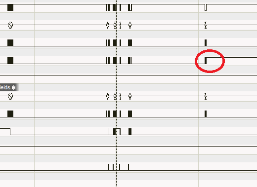
    While this doesn't show up in there, on checking about the TX boundary (even though stop condition is a parallel mode thing) I did notice something strange with your capture. For whatever reason, when the IRQs stop firing, MOSI is being held high despite the last bit being '0'. I don't know for sure but given how that has impacted the device before with the 'extra RX bytes' situation... Can you try and make sure MOSI is kept low after transmissions?

    This is a stab in the dark, but one that I could see working based on my experience with the device...