This thread has been locked.
If you have a related question, please click the "Ask a related question" button in the top right corner. The newly created question will be automatically linked to this question.
Hey,
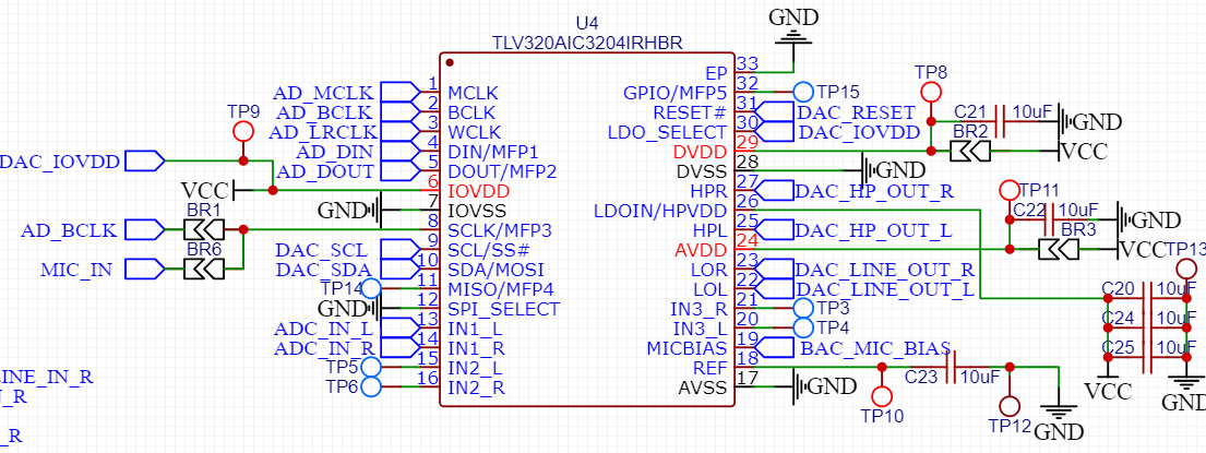
My project uses an TLV320AIC3204 audio codec chip connected to the CC8531. One board acts as a stereo USB sound card (in and out so 4channels) and another board uses the codec chip
After my battles to make the boards pair with each other I've stumbled onto another issue.
After a lot of probing around trying to figure out why I couldn't get audio working even tho the remote hid volume control worked, I saw that even tho I was getting all the clock signals (BCLK, WCLK and MCLK) the A0,A1,A2 lines were all low
I compared the config files that I had with ones I found on the internet, and it appears that everything is correct I'm still attaching them if anyone wants to double-check
Now the schematic
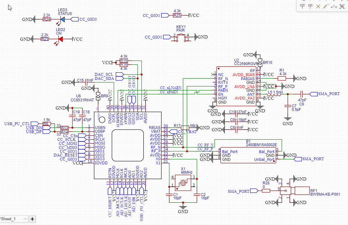
In the schematic there is a few bridges, BR9 is bridged and the others are not. Also, a CC2590 is soldered instead of the matching balun but as I said this part works fine
I'll appreciate any help, I can't be that far from the end of a working prototype.
PS: I've seen that the TLV320AIC3101 and was wondering what were the main differences with the one I'm currently using and what would be the best option
Hi,
Could you indicate how the TLV320AIC3204 audio codec is configured? I mean, I guess you are using I2C, but what are the parameters set?
In your case, which device produces the signals BCLK, WCLK, MCLK, A0,A1 and A2?
Regards,
The CC8531 is generating those signals.
The TLV320AIC3204 is autoconfigured by the CC8531 the settings are I2S, 16bits and the clock are auto calculated the I2C init commands are using the default of the CC8531 for the TLV320AIC3204
The TLV320AIC3204 does work tho, if I scratch a 3.3v wire on the DIN pin I do get some scratchy noise on the audio out.
My issue is that the CC8531 don't output anything
Well I know for sure that the CC8531 master is paired with the slave one and there is sound going to the master.
I have no idea if the slave board actually receives the audio data, I think it does because it is capable of sending the hid controls back to the master board, but I don't have a way to check for sure do you know of any ?
Samuel
Hi Samuel,
Could you specify which signals are "A0,A1,A2 lines" you refer to? I only think about AD_DIN and AD_OUT.
In addition, when you have a signal on the microphone entry of the board, do you see some activity on the AD_DIN and AD_OUT signals?
Have you verified that no error has been made between the line IN and line OUT at one point?
Regards,
The A0 A1 A2 lines I refer is the audio I/O lines of the CC8531
And I've just realized the confusion, AD_DOUT is A0, AD_DIN is A1, A2 is referred as USB_PU_CTL but on the slave board just goes to a test point
You are maybe thinking that something is wrong with the TLV320AIC3204 tho I have "tested" the TLV320AIC3204, by scratching +3.3v on the DIN port, and it does output noise, so I'm thinking it's configured correctly.
To correct myself, I have probed the 3 I/O line of the CC8531 (with and without the TLV320AIC3204 connected) and none appear to output a signal it's just flat. This is why I've included the PPWC config files I'm thinking that it must be a configuration issue either on the slave or the master board
To answer your question I've just check and the TLV320AIC3204 does output data on the AD_DOUT line, I've tested on the config I sent and the sound isn't transferred to the computer, so either I have done something wrong in my schematic either the config is wrong
Hi,
I tried to review your configuration and your schematic and I could not identify any issue. I have asked some help from some colleagues, I hope I will get their feedback by the end of the month.
In the meantime, you may want to review other threads such as this one, this one , and this one to see if you could get some ideas.
Best regards,
So good news, bad news
I've looked at the post you mentioned and in the last one they mentioned example config files which I didn't know existed, so I first loaded the USB headset (stereo out, mono in) example and it worked, for 1sec and then stopped I then tried the USB headphone example, and it worked "way better" I managed to get a continuous audio stream for 1min, and it stopped working then.
But when I tested that I had the AIC on an breakout board and after soldering it back it didn't work anymore so there might still be a schematic issue
The only BIG issue is that while it worked, the board antennas need to be positioned just right and no more than 20 cm apart
So it might be a PCB issue because I'm not good with PCB rf design (I know I can submit it here jut didn't do it for this one)
I'll keep looking thanks a lot for your help already
Samuel
Hi Samuel,
Thank you for the updates.
I am going to ask you to close this thread. If needed, you can open a new one to discuss the RF design problems with the proper experts.
Best regards,