This thread has been locked.
If you have a related question, please click the "Ask a related question" button in the top right corner. The newly created question will be automatically linked to this question.
Hello !
I had a bit of trouble lately to get some firmware for a CC1101 module running, though mostly because of my own fault...
I am using a Cortex M - MCU to drive the device directly via SPI, and register access.
My question is regarding the returned "chip status", i.e. the status value returned with each first SPI byte transferred.
I am trying to send by first filling the Tx FIFO via bust SPI transfer and then issuing a STX strobe, both transfers always returned 0x0F as status (RDY, IDLE state, FIFO free).
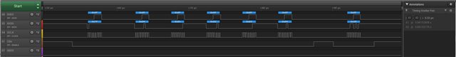
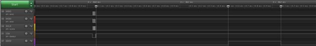
Finally attaching a logic analyzer and checking the transfers, I could not only confirm proper values, but also saw a proper pulse on the GDO0 pin.
Using the default configuration, GDO0 signals the start and end of transmission.
The pulse started about 2us after the STX strobe, with a duration of also about 2us (32 byte transfer).
My question is - a chip status of "TX" is only returned during actual transmission, between the rising and falling edge of GDO0, right ?
The datasheet is not very clear in this regard, I would say.
I suppose the same would apply to Rx, though without arriving packets it would be easier to catch a "Rx" state.
I am not sure I understand your question and/or your observation.
The default configuration (reset value) of IOCFG0 is 0x3F. This means that the s CLK_XOSC/192 is output on the GDO0 pin.
The typical settings from SmartRF Studio set IOCFG0 to 0x06. This means that the signal is asserted after sync has been sent, and de-asserted when the complete packet is sent. I assume this is the signal you are referring to, since you say that " GDO0 signals the start and end of transmission".
You do not say anything regarding which settings you are using for the radio (is calibration enabled, how many preamble and sync bytes are you transmitting, what is the data rate), but assume you use the recommended 100 kbps settings from SmartRF Studio and want to transmit a packet that is 5 bytes long (length byte + 4 payload bytes):
With the settings from SmartRF STudio, the radio will transmit 4 bytes of preamble and 5 bytes of sync before the length byte and the payload and the CRC. It will also perform a calibration of the synth when going from IDLE to TX:
Time from Strobing STX until GDO0 is asserted = (IDLE to TX time) + time to transmit preamble + time to transmit sync
= 799 us + (4*8)/100000 + (4*8)/100000 = 1.439 ms (A1 to A2 in the figure below)
The GDO0 signal will be asserted for the duration of the length byte + payload + CRC = (1 + 4 + 2)*8/100000 = 560 us (A2 to B1 in the plot above).
If you poll the status of the radio during TX (from 800 us after the STX strobe, until GDO0 is de-asserted), the STATE[2:0] bits of the status byte will indicate TX state.
Siri
Hello,
first, thank you for the quick response.
The default configuration (reset value) of IOCFG0 is 0x3F. This means that the s CLK_XOSC/192 is output on the GDO0 pin.
You are right - not quite the correct term I used.
It is the typical setting, IOCFG0D = 0x06.
You do not say anything regarding which settings you are using for the radio (is calibration enabled,
I started from a TI example, downloaded as "swrc021f.zip", more explicitely the "link" example with the "FREQ_868_CC1101" settings.
For reference, the example is in swrc021f.zip\C51\Examples\Chipcon\srf04\CCxx00\ex_link.
At the moment, I am about the compare these settings with others I generated via SmartRF Sdudio myself.
I have ported the relevant parts of the code to my MCU(s), which are Cortex M (STM32), so it's certainly different.
At this point, I can see my CC1101 register settings taking effect - or so I think, I read them back to check.
And using an endless TX loop and a SDR application, I can see some actual transmissions at 868MHz happen.
Having two identical setups, I use one as sender and try to receive with the other.
I can see the transmitter reports Rx mode when I call the receive function, but it can't manage to receive any packet yet.
Address is set to 0, with address check is off. Packet length is set to variable length mode.
I am still working through the datasheet, and did not get every detail, I guess.
At the moment I wonder about the FIFOTHR setting, which is 0x07 in my case. And I am trying to send 32-byte packets.
For reference, me runtime register dump. I learned the hard way that one cannot read back the PARTNUM register with a single-byte read ...
-- config regs --
29 2E 06 07 D3 91 FF 04
05 00 00 0C 00 21 62 76
2D 3B 13 22 F8 62 07 30
18 1D 1C C7 00 B0 87 6B
F8 B6 10 EA 2A 00 1F 41
00 59 7F 3F 88 31 09 00
-- status regs --
-- 0F 4F 3F 1F 2F 0F 0F
0F 0F 0F 0F 0F 0F 81 00
Regarding the FIFOTHR, what are you using that for?
If you are basing your code on the ex_link, this does not use the threshold.
The simplest code you can write to transmit and receive a packet using the CC1101 is the following:
1) Do a manual reset as explained in section 19.1.2 in the data sheet
2) Write the recommended registers for one of the recommended PHYS in SmartRF Studio
for example
// Address Config = No address check // Base Frequency = 867.999939 // CRC Autoflush = false // CRC Enable = true // Carrier Frequency = 867.999939 // Channel Number = 0 // Channel Spacing = 199.951172 // Data Format = Normal mode // Data Rate = 249.939 // Deviation = 126.953125 // Device Address = 0 // Manchester Enable = false // Modulated = true // Modulation Format = GFSK // PA Ramping = false // Packet Length = 255 // Packet Length Mode = Variable packet length mode. Packet length configured by the first byte after sync word // Preamble Count = 4 // RX Filter BW = 541.666667 // Sync Word Qualifier Mode = 30/32 sync word bits detected // TX Power = 0 // Whitening = false // PA table #define PA_TABLE {0x50,0x00,0x00,0x00,0x00,0x00,0x00,0x00} static const registerSetting_t preferredSettings[]= { {CC1101_IOCFG0, 0x06}, {CC1101_PKTCTRL0, 0x05}, {CC1101_FSCTRL1, 0x0C}, {CC1101_FREQ2, 0x21}, {CC1101_FREQ1, 0x62}, {CC1101_FREQ0, 0x76}, {CC1101_MDMCFG4, 0x2D}, {CC1101_MDMCFG3, 0x3B}, {CC1101_MDMCFG2, 0x13}, {CC1101_DEVIATN, 0x62}, {CC1101_MCSM0, 0x18}, {CC1101_FOCCFG, 0x1D}, {CC1101_BSCFG, 0x1C}, {CC1101_AGCCTRL2, 0xC7}, {CC1101_AGCCTRL1, 0x00}, {CC1101_AGCCTRL0, 0xB0}, {CC1101_WORCTRL, 0xFB}, {CC1101_FREND1, 0xB6}, {CC1101_FSCAL3, 0xEA}, {CC1101_FSCAL2, 0x2A}, {CC1101_FSCAL1, 0x00}, {CC1101_FSCAL0, 0x1F}, {CC1101_TEST0, 0x09}, };
TX:
3) On your TX board, write the length byte (32) + 32 payload bytes to the TXFIFO
4) Strobe STX
RX:
3) Strobe SRX
If you are monitoring your boards, you will see that GDO0 is asserted and de-asserted on both the RX and RX board.
If nothing is happening on this pin on the RX boards, it means that the radio did not receive a packet.
If you are not receiving anything, there might be problems with your HW. Have you made the boards yourselves, and if yes, what ref. design have you followed.
Siri
Thank you for the quick response again ...
Regarding the FIFOTHR, what are you using that for?
If you are basing your code on the ex_link, this does not use the threshold.
I suppose it has no real impact, at least as I understand it.
The simplest code you can write to transmit and receive a packet using the CC1101 is the following:
1) Do a manual reset as explained in section 19.1.2 in the data sheet
I am going to try that.
As mentioned, I had seen the GDO0 asserting for a Tx attempt, using a logic analyzer.
I had foolishly tried it via single-step in a debugger before ...
Until now, I have not been able to properly receive a packet.
I will try this with your suggested settings, and confirming proper sending via RTL-SDR application.
As for the config settings, I used mostly those from the Link-example, except with the PKTCTRL0 / PKTCTRL1 and PKTLEN values.
I had created register settings with SmartRF Studio, but they are basically identical.
The hardware I use are commercial boards, the wiring is done by myself.
A link to shop ad for module, (not in English, though) : www.makershop.de/.../
These modules are advertised for 868MHz.
As I understand it, the signal frequency is not limited by the CC1101, but probably by band filters on the board.
I have no schematics of this boards.
Though I get a reasonable SPI response from the transmitter chip, and see the quartz oscillator (26.0MHz) matchess the SmartRF Studio default and mentioned Link example settings.
As antenna, I have soldered in a wire of about 6,5" (ca. 17cm).
PS:
Checking the SmartRF Studio register settings, I see quite a few documented registers missing.
I assume these values will have no real effect on frequency, modulation and packet settings, and will remain on the documented defaults.
Ok. Use the settings from SmartRF Studio. Only write to the registers that are shown in the code export. For the initial test, do not do anything to the PKTCTRL0 / PKTCTRL1 and PKTLEN registers (not needed to transmit a packet of 32 bytes).
The settings you get from Studio configures the radio for variable packet length mode, meaning that you need to write the packet length as the first byte to the TXFIFO:
for example: 32, Data1, Data,2, ....., Data31, Data32 (33 bytes in total written to the TXFIFO)
I am not familiar with the HW you are using, but I would assume that when it is for 868 MHz, it could be used in the entire band (779 - 928 MHz).
Siri
Ok. Use the settings from SmartRF Studio.
The settings you get from Studio configures the radio for variable packet length mode, meaning that you need to write the packet length as the first byte to the TXFIFO:
I first tried both, and then only the second - adding the packet length as the first byte.
And the second point was my problem - with a proper length byte, packet reception works.
Thus the frequency, modem and packet config settings were not the problem per se, but the proper implementation.
I had experimented with address check, PCTCTRL settings and packet length, but obviously not in a proper way.
While I had noticed these extra configuration-dependant bytes (address, length) of a packet in the datasheet, it escaped my somehow ...
With reception now basically working, my remaining points are easy to resolve.
Thanks,
Frank
PS:
I am not familiar with the HW you are using, but I would assume that when it is for 868 MHz, it could be used in the entire band (779 - 928 MHz).
While I am a SW guy and no HW / RF expert, these look like only R and Cs. Probably a first-order band pass to limit interferences with other bands.
I suspect a semi-commercial design targeting Sparkfun & Co, which basically implements TI's reference schematics from the datasheet.
Locating schematics for the board is on my list, too.
If I might add a related follow-up qestion ...
If variable size packets are enabled and a proper length byte is prepended on Tx side, this length byte is not consumed on Rx side by the transmitter, right ?
In other words, it is left in the Rx FIFO, and has to be processed by the MCU.
The datasheet explicitly states that address bytes (if enabled) are left in the Rx FIFO, as well as the two optionally appended status bytes (CRC, link, RSSI).
In regard to the length byte, the document is no so explicit.
Hi
Everything received AFTER the sync word is always put in the FIFO. When using fixed packet length mode, number of bytes put in the RX FIFO is given by PKTLEN. When using variable packet length mode, number of bytes received in the RX FIFO is given by the length byte (first byte received after sync).
Siri
The reason for my question were somewhat confusing observations during debugging.
Continuing to debug after my post, I was able to drill down a bit deeper.
And I observed that for the very first Rx packet, the length byte is "missing".
The RXFIFO register reports one byte less, and the length byte is really missing in the data read from the FIFO.
The setup uses variable length mode (PKTCTRL0 = 0x05, PKTCTRL1 = 0x0), and a fixed number of data bytes with known content (length byte, followed by 32 bytes with index = value). The Tx setup sends the same packet over and over again every second, and was running for several minutes before I started debugging the receiver.
All subsequent Rx packets were one byte longer, and prepended with the length byte as expected.
The packet contents are otherwise correct in both cases.
Not that it bothers me much, but can't find any hint about that behavior in the datasheet of the errata document.
My receive code is almost the same as in the TI example. Function names, typedefs and comments are mostly left as is:
uint8_t PckReceive (BYTE *rxBuffer) { UINT8 pcklen, bytes; halSpiStrobe (CC1101_SRX); // wait for GDO0 to toggle wait_GDO0_high (); wait_GDO0_low (); // this status register is safe to read since it will not be updated after // the packet has been received (See the CC1100 and 2500 Errata Note) bytes = (halSpiReadStatus (CC1101_RXBYTES) & BYTES_IN_RXFIFO); if (bytes == 0) return 0; // Read data from RX FIFO and store in rxBuffer if (bytes <= BUFFER_SIZE) { halSpiReadBurstReg (CC1101_RXFIFO, rxBuffer, bytes); return (bytes); } // ...else halSpiStrobe (CC1101_SIDLE); halSpiStrobe (CC1101_SFRX); // Flush RX FIFO return FALSE; }
If you use the recommended settings from SmartRF Studio, they use variable packet length mode and appends 2 status bytes.
That means that if you start off with an empty RXFIFO and you do not check the FIFO before the packet received signal has been asserted, then you can read the NUM_RXBYTES from the RXBYTES register.
If the length byte is 32, RXBYTES will be 35 (I length byte (32), 32 payload bytes and 2 status bytes)
If you send the following packet:
0x20, Data1, Data2, …, Data32, CRC1, CRC0
It will not be possible that you receive Data1, Data2, …, Data32, Status1, Status0, and that RXBYTES is 34
If RXBYTES is showing 34, that means that there is an error in the length byte, and that the first byte in the RXFIFO is 31 (0x1F).
If you have a test case where you are using the recommended settings and are reading 34 from RXBYTES, and are reading something else than 32 from the first byte in the RXFIFO, please share an SPI plot showing this.
Siri
Sorry,
debugging took me a bit longer lately.
I checked the number of bytes sent and the order, but there seems no bug as I suspected first.
But I added an Rx-FIFO flush before entering Rx mode, and the result is now consistently the same.
Which means the first packet does not differ from the subsequent one's.
For sending 33 byte (32 data bytes + prepended size), I receive 34 bytes.
The regarding settings are PKTCTRL0 = 0x05, PKTCTRL1 = 0x00 (CRC enable, variable size, no address check, no append, no autoflush).
Writing the Tx packet and reading the Rx FIFO is done in one bust access.
I print the relevant values out on the debug console, whihc look like this:
RXBYTES = 22
pck data:
21 00 01 02 03 04 05 06 07 08 09 0A 0B 0C 0D 0E
0F 10 11 12 13 14 15 16 17 18 19 1A 1B 1C 1D 1E
1F FF
RXBYTES = 22
pck data:
21 00 01 02 03 04 05 06 07 08 09 0A 0B 0C 0D 0E
0F 10 11 12 13 14 15 16 17 18 19 1A 1B 1C 1D 1E
1F 8C
RXBYTES = 22
pck data:
21 00 01 02 03 04 05 06 07 08 09 0A 0B 0C 0D 0E
0F 10 11 12 13 14 15 16 17 18 19 1A 1B 1C 1D 1E
1F 93
All values are hexadecimal.
The "RXBYTES" value is the status register content.
The first data byte is the size, which is what I write in the send routine.
Not sure what the additional last value is, I had disabled the APPEND_STATUS bit.
And since a CRC would be the same for identical data, it can't be a CRC either.
If the length byte is 32, RXBYTES will be 35 (I length byte (32), 32 payload bytes and 2 status bytes)
I interpret that in such a way that I should expect 33 (0x21) in my case, i.e. with append disabled.
Or is that not correct ?
I am not sure I understand what the problem is.
The first byte you (the radio) receives after sync is 0x21 (33) and after that it puts the next 33 bytes on the air. That means that in total, 34 bytes are put in the RX FIFO, and this is what the RXBYTES register correctly shows as well (0x22 = 34) (no status bytes appended)
Are you claiming that you are writing another length byte than 0x21 in your TXFIFO?
If you are please share with me SPI plots (all 4 lines) for both your TX FIFO writing, and STX strobe, and also the SPI communication on the RX side.
Hello, not sure if I understand this either ...
I actually write 33 bytes (0x21) - a length byte first, and then the 32 (0x20) data bytes.
Thus I would expect to receive 33 bytes, and not 34.
I am not sure what that extra byte (at the end) is.
What I did in the meantime.
Reading back the TXBYTES register value from the sender immediately before the TX strobe, I got 0x21 / 33, as expected.
Setting both sender and receiver to fixed packet length (PKTCTRL0 = 0), I got the expected result, 32 bytes.
The first byte you (the radio) receives after sync is 0x21 (33) and after that it puts the next 33 bytes on the air. That means that in total, 34 bytes are put in the RX FIFO, and this is what the RXBYTES register correctly shows as well (0x22 = 34) (no status bytes appended)
This is the point I don't fully understand.
As you word it, this seems to mean the length byte itself is <not> included in the length value. So, for 0x20 following data bytes, I have to give a value 0x20, and not 0x21, right ?
I used to include the length byte itself - which is probably not correct.
And explains a lot - this random last byte is than probably a padding byte, or content of of the unwritten Tx FIFO.
Thus I suppose the issue was datasheet interpretation on my side.
I could set up a logic analyzer session, and provide the PulseView result file, or screenshots.
Though I think it might not be necessary.
If this is indeed correct, and including the length byte itself in the count is incorrect, you could mark this thread as solved.
Thank you, and sorry for any inconvenience ... ;-)
if you want to transmit 32 payload bytes your length bytes should be 32:
To the TX FIFO you should write this:
0x20, // Length 0x01, 0x02, 0x03, 0x04, 0x05, 0x06, 0x07, 0x08, 0x09, 0x0A, 0x0B, 0x0C, 0x0D, 0x0E, 0x0F, 0x10, 0x11, 0x12, 0x13, 0x14, 0x15, 0x16, 0x17, 0x18, 0x19, 0x1A, 0x1B, 0x1C, 0x1D, 0x1E, 0x1F, 0x20 // 32 bytes of payload
This is a total of 33 bytes (1 length byte + 32 payload bytes) and TXBYTES should be 0x21
If you are writing 0x21 as the length byte and the 32 bytes more to the TX FIFO, the TX FIFO will underflow, and on the RX side you will receive 34 bytes (since the length byte is 0x21), and your last byte will be noise as this is something not sent by your transmitter (which has underflowed).
Siri
You are correct.
Trying it out with variable packet length and a correct length byte (0x20), it works as expected - all RXFIFO register and data values match.
As a side note, I use the same code for both sender and receiver. At least the setup part (including transmitter setup values) is identical.
I check a user button at power-up, and with button-press, the board works as sender only, otherwise as receiver only.
Send and receive loop diverge somewhat, necessarily.
Anyway - as mentioned.my issue is resolved. Thanks again.