Other Parts Discussed in Thread: CC1101, CC115L
Hello,
I recently revived a project where I want to duplicate the functionality of a (obsolete) ATA5760 device to a CC110L chip (also see https://e2e.ti.com/support/wireless-connectivity/sub-1-ghz-group/sub-1-ghz/f/sub-1-ghz-forum/1036447/trying-to-get-synchronous-serial-mode-w-manchester-encoding-to-work-so-far-getting-only-noise ).
At the moment, I do have a setup with the CC110L that works with some transmitters, but not all. I think I'm running into some issues concerning IF and bandwidth that I can't readily find an answer to.
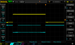
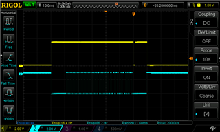
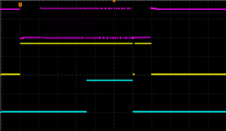
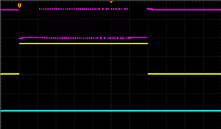
The old ATA5760 uses an IF of 950 kHz and a bandwidth of 300 kHz or even 600 kHz, but when I set those parameters in the CC110L, things don't work at all -- the carrier output (CS) does not respond, and the serial signal output just shows noise all the time. I get the best performance so far with an IF setting of ~395 kHz (FSCTRL1 = 0x0F) and a bandwidth of ~60 kHz (MDMCFG4:MDMCFG3 = 0xF637).
Unfortunately, especially older transmitters are still not picked up correctly by the CC110L, probably because their transmitter frequency is slightly different from newer products, and the 60 kHz bandwidth is too narrow. One additional problem is that I only designed the newer products, and do not have the proper RF specifications for the older ones.
As I am still not very knowledgeable about the finer details concerning digital receivers, I have some questions:
- How does the absolute receiver bandwidth (frequency range) relate to the base frequency (869.200 MHz)? Is this bandwidth centered around the Fbase -- so with the absolute frequency range of Fbase-1/2BW ... Fbase+1/2BW? Or is Fbase the lowest frequency, with the frequency range from Fbase ... Fbase+BW?
- Even transmitter products that work reliably with a 60 kHz receiver bandwidth have trouble getting through at anything over 80 kHz, even at very close range (1 meter), which I do not understand. How can this happen? A greater bandwidth should make it easier to receive various signals, not more difficult, and at this range, noise should not mess things up. Also, the datasheet mentions bandwidths of 300 kHz and more as being quite normal for this type of application.
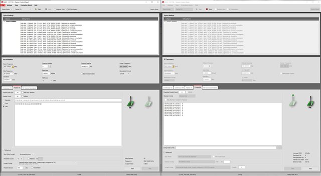
- Is the actual choice of IF important? When working with analog receivers, I know about the importance of proper IF choice, and tuning and filtering of the IF circuits, but things like the CC110L are more like a black box to me in this respect. I do have SmartRFStudio 7 working in Wine under Linux now, and I noticed that the IF frequency is apparently chosen automatically.
Thanks for any information,
Regards,
Richard