This thread has been locked.

If you have a related question, please click the "Ask a related question" button in the top right corner. The newly created question will be automatically linked to this question.

CC1312R: DMR 4-FSK application or configuration issue in the sensitivity test

Part Number: CC1312R
Other Parts Discussed in Thread: CC1201, CC1200, LMX2571

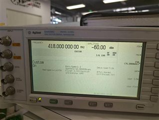
The sensitivity test is carried out using the demo board of CC1312R, and the signal after code modulation is sent by the RF signal generator to the board. 2-(G)FSK is complete. Frequency is 418 MHZ,symbol  rate is 40 KBPS, deviation of 25 KHZ, the data flow of 0 x55555555930b51de2d5dc254eab46154a952bac07e06, 0 x55555555 is preamble word, 0x930b51de is sync word and 0x7e06 is CRC word.
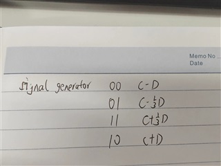
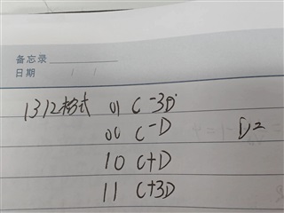
After switching to 4-FSK application, the test found that cc1312 and RF signal generator are different in 4-fsk encoding format, and the definition of frequency deviation is different, the frequency deviation of RF signal generator is three times that of CC1312, please see the attachment for details.

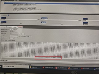
So the deviation in the generator has changed to the 75Khz, and the code in the generator changed to 0x00000000c65e048b78089701bfe13403f807ef950b53,but the software can't get the correct data. Then i changed the sync word from 0x930b51de to 0x00, i can see the complete data in the text box. 

Is this the configuation issue or 4-FSK application issue?

  • A couple of things to note:

    - The sync word should be 2-FSK coded (I believe if you look at the standard sync word that you are using that the inner symbols are not used.

    - For CC1312R the deviation is given for the inner symbols:

    "Note that the deviation is then set as the deviation of the inner symbols, meaning if you want the deviation to be 50 kHz, modulation.deviation = (50000/3)/250. 250 Hz is the step size for nominal settings. For 4-GFSK the modulation index for inner symbols should be >= 1/3. Lower modulation index will degrade sensitivity significantly"

  • In the 4FSK application, the deviation should be 1/3 of the origianl 2-FSK.

    i have changed the deviation in the RF generator from 25Khz to 75KHz, the deviation in the CC1312 configuration is still 25Khz. Of course, I can also change the deviation in CC1312 to 1/3 of the original.

    How can i change my sync word to fit 4-fsk application? The original sync word in the 2-FSK mode is 0x930b51de,8 bytes. What should it be in the 4-FSK mode in the SmartRF Studio tools.

  • Do you have a spectrum analyzer where you can compare the spectrum from the generator and the CC1312R  with the settings you are currently using? 

  • YES, there is a SA in the lab. The frequency deviation of each data can be seen through SA(Testing the deviation by sending the same data).  The below 4fsk coding format is got by the SG, SA and CC1312.

    4FSK mode in CC1312, deviation= CC1312 deviation

    01=CARRIER-3*Deviation

    00=CARRIER-Deviation

    10=CARRIER+Deviation

    11=CARRIER+3*Deviation

    4FSK mode in the SG, deviation= SG deviation

    00=CARRIER-Deviation

    01=CARRIER-1/3*Deviation

    11=CARRIER+1/3*Deviation

    10=CARRIER+*Deviation

     So i changed the data to fit the 4-fsk coding format. When i set the sync word to 0x00,i can see the correct data in the above attached picture. But when the sync word changed back to the 0x93 or the 8bytes word, the text box is blank.

  • SG1312

    The first picture is from CC1312 demo board and the second picture is from SG.Based on the two pictures, i have no more found.

  • They look equal meaning that the modulation looks to be correct. 

    Are you able to look at the start of the transmission in the time domain with your spectrum? 

    If you set the sync word to either 0xAAAA or 0x5555 (16 bit) in Smart RF Studio, what do you receive? 

  • There is no output when the sync word is 0xAAAA, 0x5555, 0xFFFF(16 bit). When the sync word is 0x0000, i can see the output in the text box,similar with the attached picture in the above question.

  • When the demo board is set to the 4FSK mode, the sync word will be strange.Even if I can see the data from the text board and input one word as a sync word, there will be no display.

    i use a strange way to test 4FSK sensitivity, it should be lower 6 dB than the 2FSK. Is it normal?

    Could you please test CC1312 demo board 4FSK sensitivity in your lab and share the configuration?
  • Hi Yuang,

    Could you try this?

    Use the same deviation as before. Set the preamble of CC1312 to 1 byte, and the sync word to 0xaa aa aa aa. Then chose fixed length of e.g. 10 bytes.

    Then send the following with your signal generator in 4FSK:

    Preamble: 0x2222

    Sync word: 0x2222 2222 2222 2222

    Payload: 10 bytes

    Are you receiving with this configuration?

  • If it did not work, could you try with preamble 0x7777 and sync word 0x7777 7777 7777 7777?

    Regards,

    HG

  • I have tried this. Symbol rate is 50kbps and deviation is 25KHz(SG and CC1312 configuration is same). The data flow is high, so it should be the data sent by the signal generator.

  • Hi Yuyang,

    I believe if you send 0xD75F55DF7757F7FD as the sync word and 0x7777 as the preamble, you will receive when using our default sync word 0x930B51DE and preamble of 1 byte. This sync word used only the outer symbols of the 4-FSK modulation.

    Regards,

    HG

  • Hi, Halatullah.

    This sync word and preamble is not fit for 0x930b51de and 1 byte preamble in 4FSK mode. I test several times and have confirmed the coding format for preamble words and sync words. As I confirmed before, the deviation in the SG(Agilent E4438C) should be three times than the CC1312 demo board then they have the similar output spectrum. This is also fit for the RX 4FSK mode. 

    For the preamble and sync words, 

    SG    1312

    10   =    1;

    00   =    0;

    So 0x930b51de in 1312 demo board is equal to 0x820A008A2202A2A8 in this SG.

    Now i can test the sensitivity in our lab.

    I have another question about this board.

    For carrier is 418MHz, symbot rate=6.5Kbps,deviation=2Khz,RX BW=12.2Khz, 2FSK mode, the sensitivity=-119dBm

     For carrier is 418MHz, symbot rate=6.5Kbps,deviation=0.641Khz,RX BW=12.2Khz, 4FSK mode, the sensitivity=-113dBm

    Same RX BW and NF is same too, this 6db deviation should be the higher SNR needed for 4FSK. Is it right?

  • Hi Yuyang,

    Since the deviation of the inner symbols of the 4-FSK symbols is smaller compared to the 2-FSK symbols, you will get degraded sensitivity for 4-FSK. Assuming that you use the same data rate (not symbol rate), you could use smaller RX bandwidth for 4-FSK compared to 2-FSK. This will again increase the sensitivity of 4-FSK. But overall, you will have a slightly degraded sensitivity for 4-FSK.

    Regards,

    HG

  • As the DMR frame format requirements,  the sync word is in the  middle and it has data sync and sound sync. Does this chip support the payload transparent transmission in the 4-FSK mode? Or is there any SUB-1G chip supported this kind of solution. The CPU will do the data processing.

  • Hi,

    None of our devices supports this data format. Our CC120x families has a operation mode called synchronous serial mode that can be used to receive this packet format. However, it cannot be used for TX operation. Read more about this mode in section 8.9 of https://www.ti.com/lit/ug/swru346b/swru346b.pdf?.

    Regards,

    HG

  • Hi,

    As DMR physical layer requirements, the symbol rate is low, 4.8k bauds and the bit rate is 9.6kbps, the deviation is 1.944khz, the channel bandwith is 12.5KHz. So I need a narrow band and low data rate component for this product. CC1201 has big RX bandwith, it can' t be less than 50KHz

    Is there any component supported this application?

    Regards

    YY

  • Hi,

    The rx bandwidth of CC1200 goes all the way down to 9.5 kHz.

    Do you only want to receive or transmit too?

    Regards,

    HG

  • Only for receiving,cc series chip cannot support this application, i will use lmx2571 to tansmit

  • i need the transparent transmission for RX payload. The configuration is 

    IOCFGx.GPIO1_CFG = SERIAL_CLK (8)

    IOCFGx.GPIO2_CFG = SERIAL_RX (9)

    SYNC_MODE = 0

    is there any other configuration?

    When the RSSI value is over the Silence threshold,  I will processing the data to check if the data trigger the sync word. Is it OK?

  • Hi Yuang,

    There are a few more settings that need to be set that are listed in section 8.9.1 of the user guide. 

    In SmartRF Studio, you can select Continuous RX and then Synchronous serial mode. That will give you the right settings.

    When the device gets a signal level above carrier sense threshold, it will send it through GPIO2 in your case to the MCU on the falling edge of the clock. You need then to read the data on the rising edge of the clock.

    Regards,

    HG

  • A question about the protocol: Is it an option to loose the first half of timelot1 and use the sync to receive the second half of timeslot 1 and the first half of timeslot 2 and so on? 

    On CC1200, using serial sync mode without sync word does not give good performance. 

    A note on TX: You can send whatever you need to send be setting preamble/ sync off and place everything in the TX buffer. 

  • SYNC words is not unique, includes the voice sync and data sync,the base station sync and handheld station sync. The signal processing unit needs to determine where this comes from, which type of sync, and then process the data.

    4FSK is not supported in the synchronous serial mode on CC1200 TX, preamble words and sync words can't be removed based on the userguide.

  • Hi, Halatullah.

    You means that when the signal level is above the sense threshold, the RX data will trigger voltage changed,  then it means that the data is valid then i start to read the RX data on the rising edge of the clock.

    Or i need to configurate a new GPIO to confirm the enable signal.

    Which one is right?

  • Hi,

    The data is continuously set on the GPIO on the falling edge of the clock no matter how weak the RSSI is. So you need to constantly read and process the data on the rising edge of the clock. If you don't want to process the data all the time as a lot of it is just noise, you can utilize carrier sense (CS). You can use CS as an interrupt for when to start processing data. You need to set the CS threshold very close to the sensitivity level as it will limit the sensitivity. 

    In this case, if you you set the CS threshold at e.g. -100 dBm, you will not be able to receive anything above -100 dBm.

    Regards,

    HG