This thread has been locked.

If you have a related question, please click the "Ask a related question" button in the top right corner. The newly created question will be automatically linked to this question.

Excel sheet to estimate range for Indoor and Outdoor

Other Parts Discussed in Thread: CC2520, CC2530, CC2538, CC2540, CC2541, CC2543, CC1190, CC1125, CC1120, CC2544, CC2545, CC2500, CC2564, TIDC-CC1120-LRM-868-915MHZ, CC1310, CC2640, CC-ANTENNA-DK2, CC1350, CC2640R2F, LAUNCHXL-CC2640R2

Hi,

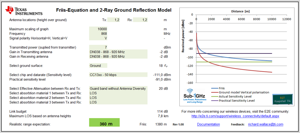
The attached excel sheet helps to estimate a practical range estimation for indoor and outdoor radio links.

This has been used a lot in TI seminars and is a helpful tool for calculating a realistic range expectation.

Latest version Rev 1.20:

SWSC002B -Range Estimation for Indoor and Outdoor Rev1_20.xlsm

and available at: http://www.ti.com/tool/rf-range-estimator

Any feedback is welcomed.

Regards, Richard

  • Hi,

    What version of Excel should be used for this sheet? It seems I do not have any options to select in some cells. I use Excel 2007, macros are allowed.

    Screenshot is attached.

  • Range Estimation for Indoor and Outdoor Rev1_06 - Excel 97-2003 version.xls

    Hi,

    The version is Microsoft Excel 2010. Attached is an Excel 97 - 2003 version. Let me know if this solves the issues.

    Regards, Richard

  • It seems I see the same result (wrong one) . Could you post screenshot of this Excel Sheet as it works on your PC and provide brief comments - which cells could be modified by customer?
    Br,
    Oleg
  • Hi,

    there will be an app note released soon that describes all the parameters in this excel calculation. All the grey zones are input fields which can be selected via drop down menus or by just entering a value.

  • The fields that are shown in grey are the input fields. The heights of the Tx antenna (h1) and Rx antenna (h2) are entered at the top; for hand-held devices this is typically in the region of 1.2 m. The scaling of the graph is just for the figure scale shown on the right hand side and this is flagged in red if the scale is less than the calculated range for Friis and the ground model (2-ray). The frequency field is the operating frequency of the radio. For the signal polarity, “V” for vertical polariztion and “H” for horizontal polarization can be entered. The conducted transmitted output power should then be entered and this is normally between -20 dBm to +30 dBm pending the radio solution. The gain for the Tx antenna (GT) and Rx antenna (GR) must be entered; for a perfect matched dipole this is 2.1 dB, if this is unknown keep this value between 0 dB and 2.1 dB. There is a list of antennas which can be chosen with a recommended value for the gain; the gain in the list varies from -6 dB to +2.1 dB. The surface (εr) shown in figure 1 can be set between Ground (εr = 18), Water (εr = 88) and Sand (εr = 2.5); if this is unkown then keep this at a typcial value of 18.


    For the sensitivity level of the radio, a list is available of the various radios and the data rate settings. The data rate setting is important since this determines the actual senisitivty level of the radio for a particular date rate. A larger data rate will always have a lower sensitivity level (-174 dBm + 10log10(BW) ).


    Bandwidth (BW)

    Theoretical sensitivity level

    1 Hz

    -174 dBm

    1 kHz

    -144 dBm

    1 MHz

    -114 dBm

    Sensitivity level decreasing with increasing bandwidth


    The list of radios with data rates supported in the excel ver1.06 release is shown in Table x. If a specific radio and data rate cannot be found then choose a setting that gives the same sensitivity level that is specified in the data sheet.


    Sub-1 GHz Devices

    Sensitivity level (dBm)

    2.4 GHz Devices

    Sensitivity level (dBm)

    CC11L - 0.6 kbps

    -116

    CC2520 - 250 kbps

    -98

    CC11L - 1.2 kbps

    -112

    CC2530 - 250 kbps

    -97

    CC11L - 38.2 kbps

    -104

    CC2538 - 250 kbps

    -97

    CC11L - 250 kbps

    -95

    CC2540 - 1 Mbps (HG)

    -93

    CC11L - 500 kbps (MSK)

    -90

    CC2540 - 1 Mbps (Std)

    -87

    CC11L - 500 kbps (4-FSK)

    -96

    CC2541 - 250 kbps (160 kHz fdev)

    -98

    CC110x - 0.6 kbps

    -116

    CC2541 - 500 kbps (MSK)

    -99

    CC110x - 1.2 kbps

    -112

    CC2541 - 1 Mbps (160 kHz fdev)

    -91

    CC110x - 38.2 kbps

    -104

    CC2541 - 1 Mbps (250 kHz fdev)

    -94

    CC110x - 250 kbps

    -95

    CC2541 - 2 Mbps (320 kHz fdev)

    -86

    CC110x - 500 kbps (MSK)

    -90

    CC2541 - 2 Mbps (500 kHz fdev)

    -90

    CC110x - 500 kbps (4-FSK)

    -96

    CC2543 - 250 kbps (160 kHz fdev)

    -98

    CC111x - 1.2 kbps

    -110

    CC2543 - 500 kbps (MSK)

    -98

    CC111x - 38.2 kbps

    -102

    CC2543 - 1 Mbps (160 kHz fdev)

    -91

    CC111x - 250 kbps

    -94

    CC2543 - 1 Mbps (250 kHz fdev)

    -94

    CC111x - 500 kbps (MSK)

    -86

    CC2543 - 2 Mbps (320 kHz fdev)

    -86

    CC1125 CC1190 - 0.6 kbps (LRM)

    -129

    CC2543 - 2 Mbps (500 kHz fdev)

    -90

    CC1120 CC1190 - 0.6 kbps (LRM)

    -126.5

    CC2544 - 250 kbps (160 kHz fdev)

    -95

    CC112x - 0.3 kbps (CG - 4 kHz fdev)

    -127

    CC2544 - 500 kbps (MSK)

    -96

    CC112x - 1.2 kbps (4 kHz fdev)

    -123

    CC2544 - 1 Mbps (160 kHz fdev)

    -87

    CC112x - 1.2 kbps (10 kHz fdev)

    -120

    CC2544 - 1 Mbps (250 kHz fdev)

    -91

    CC112x - 1.2 kbps (20 kHz fdev)

    -117

    CC2544 - 2 Mbps (320 kHz fdev)

    -84

    CC112x - 4.8 kbps (OOK)

    -114

    CC2544 - 2 Mbps (500 kHz fdev)

    -88

    CC112x - 38.4 kbps (20 kHz fdev)

    -110

    CC2545 - 250 kbps (160 kHz fdev)

    -98

    CC112x - 50 kbps (25 kHz fdev)

    -110

    CC2545 - 500 kbps (MSK)

    -98

    CC112x - 200 kbps (83 kHz fdev)

    -103

    CC2545 - 1 Mbps (160 kHz fdev)

    -91

    CC120x - 1.2 kbps (4 kHz fdev)

    -122

    CC2545 - 1 Mbps (250 kHz fdev)

    -94

    CC120x - 4.8 kbps (OOK)

    -113

    CC2545 - 2 Mbps (320 kHz fdev)

    -86

    CC120x - 32.768 kbps (50 kHz fdev)

    -108

    CC2545 - 2 Mbps (500 kHz fdev)

    -90

    CC120x - 38.4 kbps (20 kHz fdev)

    -110

    CC2500 - 2.4 kbps

    -104

    CC120x - 50 kbps (25 kHz fdev)

    -109

    CC2500 - 10 kbps

    -99

    CC120x - 100 kbps (50 kHz fdev)

    -107

    CC2500 - 250 kbps

    -89

    CC120x - 500 kbps (MSK)

    -97

    CC2500 - 500 kbps

    -83

    CC120x - 1000 kbps (4-GFSK)

    -97

    CC251x - 2.4 kbps

    -103


    CC251x - 10 kbps

    -98


    CC251x - 250 kbps

    -90


    CC251x - 500 kbps

    -82

    Table x. Sub-1 GHz and 2.4 GHz Devices Sensitivity Levels for various data rates


    The input field selection for “Select Effective Attenuation between Rx and Tx” contains a number of options which take into account the size of the guard band (link margin); and several input fields to select various construction materials normally used for indoor range prediction. The level of the guard band depends on the level of margin that is required. Theoretically, this can still be 0 dB and the radio link will still work. However, a certain guard band should be taken and this is normally in the range of 10 dB to 20 dB. For a system that requires a strong and reliable “fail safe” RF link then the margin could be increased furthermore. Similarly, for a system that can accept re-transmissions and temporary link losses then this can be reduced. With multi-path propagation effects, the signal level can vary up to 15 dB so having a guard band > 15 dB will take this into account. When not using antenna diversity then the recommended guard band is 20 dB and with antenna diversity this can be reduced to 10 dB guard band.


    When calculating outdoor Line-of-Sight (LOS) range then “LOS” can be selected for the three input field options as can be seen in Figure tbd. For improved indoor range estimation, various construction materials can be chosen for the three input field options, the choice of material is shown in Table x.


    Construction

    Material

    Attenuation (dB)

    500 MHz

    Attenuation (dB)

    1 GHz

    Attenuation (dB)

    2.4 GHz

    LOS

    0

    0

    0

    7" brick

    3.5

    5.5

    7.5

    8" concrete

    21

    25

    32

    1/2" drywall

    0.1

    0.3

    0.6

    1/2" glass

    1.2

    2.2

    3.4

    4" reinforced concrete

    23

    27

    31

    3" lumber

    1.5

    3

    4.7

    Table xy. Typical attenuation for various construction materials at 500 MHz, 1 GHz and 2.4 GHz


    As can be seen in Table x, the material penetration is highly frequency dependent and the advantages of operating at a lower frequency is clearly seen in the link budget and range expectation. A rule-of-thumb is every 6 dB increase in a link budget doubles the range distance. To send a signal through an 8” concrete wall at 1 GHz will have approximately twice the range compared to a similar system operating at 2.4 GHz.


    When all the parameters with the height of the antennas, frequency, polarization, output power, antenna gain, ground surface, sensitivity level, guard band and material between Rx & Tx; then a more realistic range can be calculated compared to the standard Friis formula.

  • Ver 1.07 supports CC13xx and CC26xx.
  • great work indeed.
  • Documentation on how to use this excel range calculation can be found at: www.ti.com/.../swra479

    Regards, Richard
  • very timely!
  • Ver 1.08: updated with support for CC2564, CC31xx and CC32xx and added link to documentation
  • Hi, Richard

    could you modified sheet to have option to set "Practical sensitivity level" to any value?

    It could be useful to compare a measured RSSI vs calculated one for specific distance.

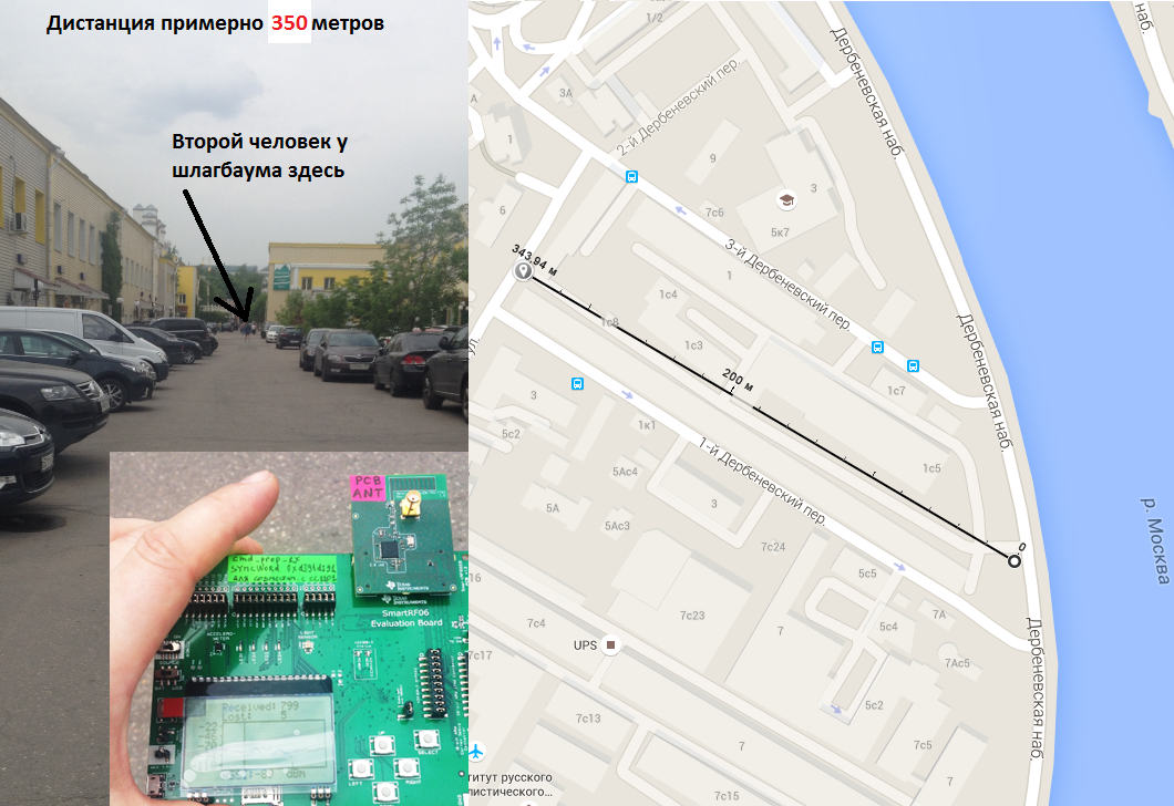
    I did CC13xx range test with DN038 antennas. My practical result is not far from your calculator. I just had to change Transmitted power in calculator (from 14 to 7 dBm) to be in comply with my real RSSI (-84 dBm vs fixed -91 dbm)

  • Hi Oleg,

    I can add this to the next release. Good to hear that there is a good correlation.

    Have updated the version to Rev 1.11 now that supports the new Long Range Modes from CC13xx and improved the accuracy of predicted range a little bit more.

    Regards,
    Richard
  • Hello richard,

    Thanks for your work, it's very interesting.

    I'm currently working with the CC1120, and I'm interested in range / sensitivty optimization.

    On the application report SWRA479, chapter4, you talk about sensitivity levels, and we can see for Sub 1Ghz devices  : CC1120 CC1190 - 0.6 Kps (LRM)

    What do you mean by "LRM", is it a way to say we must set the CC1120 register with parameters you give on table 8 ?  It don't match with the generic setting that I find in smartRF studio (in smart RF studio, we have somthing like : "Bit rate 1.2 Kbps, 2 FSK, narrowband, optimized for sensitivity)

    Thierry

  • For more details about the LRM including software and a Usermanual, see processors.wiki.ti.com/.../Category:Sub-1GHz
  • Thanks for the answer, but I wonder what's exactly mean LRM. There is a lot of information on the wiki, perhaps for C1120 LRM, but where ? 

    Since there is nothing about LRM in the CC1120 user guide, I expect that, when richard wallace talk about "CC1120 LRM", it talk about long range module, and it mean he use the "TIDC-CC1120-LRM-868-915MHZ" reference design...

    I found this :
    www.ti.com/.../TIDC-CC1120-LRM-868-915MHZ Documents

    It seems that special software is used to achieve ultra narrow band communication, where can we find more informations about software setting for LRM ?

  • See processors.wiki.ti.com/.../Cc112x_cc120x_lrm, the wiki has been reorganized a bit. Here you find the documentation and software.
  • Ok it's the good link, thanks !

    thierry
  • Hi,

    Are CC112x LRM settings the same as for CC1310 LRM?

    Will these chips (CC112x and CC1310) communicate with each other in "LRM" modes?

    Best regards,

    Oleg

  • No, CC112x and CC1310 LRM is not the same. CC112x uses narrowband (explained here: processors.wiki.ti.com/.../Cc112x_cc120x_lrm). Since CC1310 is not a narrow band device CC1310 uses DSSS for LRM.
  • Could you publish all CC1310 LRM settings? 

    I could not find any "LRM/DSSS" mention inside SWCU117D [CC13xx, CC26xx SimpleLink™ Wireless MCU Technical Reference Manual] 

    Is it possible to use CC1310 in LRM mode with CC12xx  (with needed special settings for CC12xx) ?


  • The CC1310 LRM settings can be found in SmartRF Studio, do a code export.

    No, CC12xx LRM is not compatible with CC1310 LRM.
  • hi richard,I'm doing CC1310 range test too, the result is not so good,so i'm very interested in your test.Could you provide me your test code sources?so i can compare and find out where the question is .Thank you!
  • Hi,

    If you are testing the CC1310, then please use the 625 bps, Long range mode setting in SmartRF studio.

    Let me know your range results and test setup.

    Regards,

       Richard

  • Will Wang: Have you checked the noisefloor on your location? See also e2e.ti.com/.../474018 that covers some other reasons why you see poor range.
  • hi richard:

    My testing mode is:868M, 50K SymbolRate, 25K Deviation, 110K RX Filter BW and 868M, 200K SymbolRate, 200K Deviation, 870K RX Filter BW.

    The result is 50K:470m,200K:around 300m。And the BER is below 1%, but the PER is very high,around 50%-70%.

    So I wonder if this testing is reliable?

    At last,Could you please provide me your test code resources?

    Thank you !

  • Did you measure the noisefloor at your location? 

    Did you do the test on a city street or on an open field? 

  • hi TER:
    1.Around -120dBm
    2.City street,and don't have many cars
  • Hi,

    What is the height of your antennas above the ground ?

    Are you using boost mode (14 dBm) or normal mode (12 dBm) ?

    Calculating with a height of 1m above ground. For the 50k data rate setting, then I would expect around 700 m to 800m depedning on if you are using Tx output power level of 12 dBm or 14 dBm.

    700 m - 800 m  is based upon line-of-sight. Any object between the Tx and Rx units will attenuate the signal and the range distance will be reduced.

    Regards,

       Richard 

  • hi Richard

    1.antennas above the ground is about 1.5m

    2.14dBm

    3.So,you means at the best condition,50K can achieve 700-800m.Based on this result, What kind of antennas is used for testing?Mine is PCB antennas.

    4.And what test code is used for this test?Mine is "cc13xx_range_test_kit_2_0_3_PG2.hex".

    So,if possible,could you provide me your test code?

    Thank you!

  • In the excel sheet you can select the type of antenna you want to do the estimate for. You need to select an antenna that has the same efficiency as the one you use, the excel sheet contains data for both whip antennas and PCB antennas.
  • Latest version (Rev1.12) updated with:

    - Checklist for debugging in the event of poor range
    - Better overview of realistic antenna gains for various frequencies for "hand held" devices
    - More precise range estimation

  • hi richard:

    from the excel, I see 5Kbps、LRM Mode can achieve 1.2km distance,but there is no RF Parameters included.

    So, can you please give me the 4.8Kbps or 5Kbps RF Parameters?including Deviation、RX Filter BW、TX Power、etc。

    We need this Parameters to test Range.

    Thank You!

  • Hi,

    The RF parameters can be entered into the excel sheet.

    Select the chip and datarate first. This sets the sensitivity level; the Rx filter BW and frequency deviation values are based upon the recommended settings that are specified in the data sheet or SmartRF studio default settings.

    The Tx power can be directly entered into the excel sheet.

    Is it the settings for SmartRF studio you need for 5 kbps ?

    Regards,

       Richard

  • hi richard:

    yes,I need the settings for SmartRF studio, When I choose CC1310 and set datarate as 4.8K or 5Kbps, but I don't know other parameters,like Rx filter BW and

    deviation. And SmartRF studio didn't provide the default settings about 4.8K or 5Kbps.

    Thank you!

  • Great!
  • Does this model account for a ceiling in indoors applications? Since the height from the ground is considered, I imagine the distance from the ceiling will have similar implications.

    Thanks, 

     ~Nathaly

  • Hi Richard,

    Could you please share link for Ver 1.07 as I want to use this tool for CC2640.

    Thank you.

    Regards,
    Sujata
  • hi, Richard,

    how to select the 

    Select Effective Attenuation between Rx and Tx:

    there are three options there, what do they mean respectively?

  • If you know the estimated attenuation in your use case, combine material 1-3 to get the number that is relevant in your case. Or if you know your signal is going to pass through different materials select the relevant ones. Note that the excel sheet aims to give an estimate of what you can expect in different cases. If the excel sheet says 100 m you will most likely not see 1000 m in practical measurements or the other way around.
  • Thank you Ter. I would like to understand the redundancy on TX/RX together are 40 dBm for a reliable link. This is also confirmed by putting two EB/EM CC1310 running factory PER apart of 1 meter and I get around -23 dBm with TX 12.5 dBm. Summing these two figures is 35.5, the further redundancy is about 4.5dBm.
  • Latest version (1.14) has been updated to include:
    • selected chip's blocking parameter (+/- 10 MHz) and how this effects range with an unwanted interference / jammer.
    • environment noise floor parameter since this is becoming an important factor in several countries.
    • Mean Effective Gain of antennas (measurements from CC-Antenna-DK2)

    Any feedback is welcomed.

    Regards, Richard
  • what is the password of the file? 

  • No need of password to open the file.
  • Hi,

    CC2640 is supported in the latest version.

    Select CC26xx in the drop down menu.

    Regards,

       Richard

  • Hi Steven,

    If line-of-sight (LOS) then the absorbtion material can be kept as LOS.

    The different materials between Rx and Tx is just to approximate an indoor range.

    More info at page 10 in document: www.ti.com/.../swra479.pdf

    Regards,
    Richard
  • Thank you Richard.

  • Hi,

    Could you please share the link for it.
    As in Latest version (1.14) excel file , I am not able to see the drop down menu.

    Many thanks.

    -Sujata
  • password need to edit it. The file is write protected.
  • Please see www.ti.com/.../swra479.pdf for how to use the excel sheet.

    Why do you need to edit the file? By selecting the option that is closest to your use case you will be able to do the calculations.