This thread has been locked.

If you have a related question, please click the "Ask a related question" button in the top right corner. The newly created question will be automatically linked to this question.

How to make CC1111 USB Evaluation Module Kit 868/915 MHz receive data packet sent from CC1310 Evaluation Module Kit ?

Other Parts Discussed in Thread: CC1310, SIMPLICITI

Hi, I have already bought CC1111 USB Evaluation Module Kit 868/915 MHz (www.ti.com/.../cc1111emk868-915), and  SimpleLink™ Sub-1 GHz CC1310 Evaluation Module Kit (www.ti.com/.../CC1310EMK), as shown below.

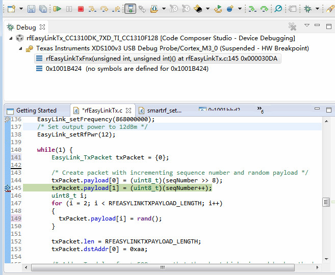
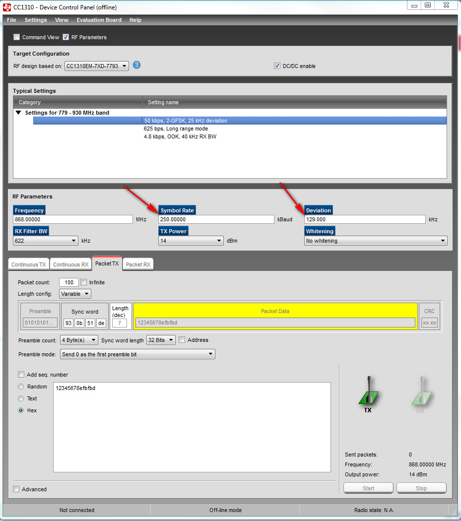
I am trying to run and debug the example project provided by TI. This project is shown below


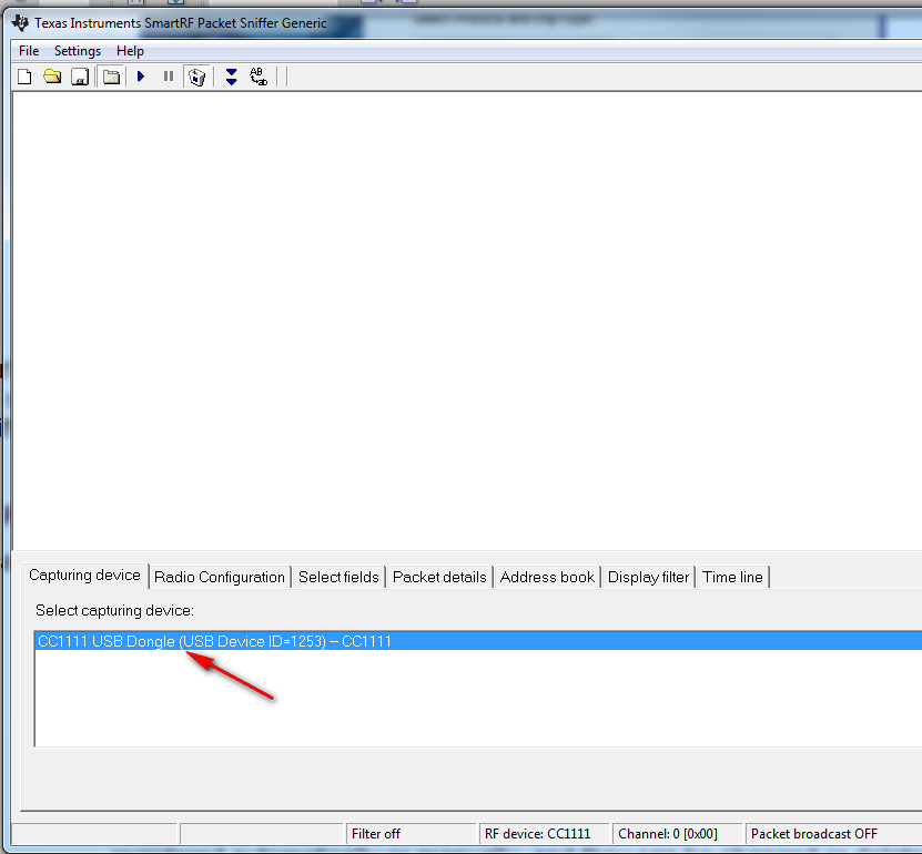
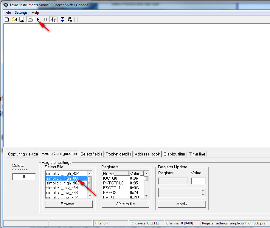
I find that CC1111 USB Evaluation Module Kit 868/915 MHz cannot receive any data packet.

Could some one provide some instructions about how to receive the packet from CC1310 by using CC1111 USB Evaluation Module Kit 868/915 MHz?


Thank you.

  • Hi,

    Sync words ( by default) are different from CC1111 to CC1310. So, use the same Sync word ( SYNC0 & SYNC1) on both devices. Also make sure both transmitter and receiver uses the same freq, data rate, modulation etc..

    You may also try increasing the Rx Filter Bandwidth on the Receiver to accomodate any tranmit frrequency offset (due to crystal tolerance) on the transmitter.

    Thanks,

    PM

  • Hi, thank you. How to know the Sync word ( SYNC0 & SYNC1) used by CC1111 USB Evaluation Module Kit 868/915 MHz? Is through the software below?

    My final aim is to know the Sync word ( SYNC0 & SYNC1) used by CC1111 USB Evaluation Module Kit 868/915 MHz and set the Sync word ( SYNC0 & SYNC1)  of CC1310 to be the same as that.

    I open the file "simpliciti_high_868.prs" provided by the software, as shown in the above figure. The content of this file is

    # Deviation = 128.906250
    # Base frequency = 868.299683
    # Carrier frequency = 868.299683
    # Channel number = 0
    # Carrier frequency = 868.299683
    # Modulated = true
    # Modulation format = GFSK
    # Manchester enable = false
    # Sync word qualifier mode = 30/32 sync word bits detected
    # Preamble count = 4
    # Channel spacing = 199.951172
    # Carrier frequency = 868.299683
    # Data rate = 249.756
    # RX filter BW = 600.000000
    # Length config = Variable packet length mode. Packet length configured by the first byte after sync word
    # CRC enable = true
    # Packet length = 255
    # Device address = 0
    # Address config = No address check
    # PA ramping = false
    # TX power = 0
    #---------------------------------------------------
    # Packet sniffer settings for: CC1111
    #
    IOCFG0 | 0xDF31|0x06|Radio Test Signal Configuration (P1_5)
    PKTCTRL0 | 0xDF04|0x05|Packet Automation Control
    FSCTRL1 | 0xDF07|0x0C|Frequency Synthesizer Control
    FREQ2 | 0xDF09|0x24|Frequency Control Word, High Byte
    FREQ1 | 0xDF0A|0x2D|Frequency Control Word, Middle Byte
    FREQ0 | 0xDF0B|0xDD|Frequency Control Word, Low Byte
    MDMCFG4 | 0xDF0C|0x1D|Modem configuration
    CHANNR | 0xDF06|0x00|Channel Number
    MDMCFG3 | 0xDF0D|0x55|Modem Configuration
    MDMCFG2 | 0xDF0E|0x13|Modem Configuration
    MDMCFG1 | 0xDF0F|0x23|Modem Configuration
    MDMCFG0 | 0xDF10|0x11|Modem Configuration
    DEVIATN | 0xDF11|0x63|Modem Deviation Setting
    MCSM0 | 0xDF14|0x18|Main Radio Control State Machine Configuration
    FOCCFG | 0xDF15|0x1D|Frequency Offset Compensation Configuration
    BSCFG | 0xDF16|0x1C|Bit Synchronization Configuration
    AGCCTRL2 | 0xDF17|0xC7|AGC Control
    AGCCTRL1 | 0xDF18|0x00|AGC Control
    AGCCTRL0 | 0xDF19|0xB0|AGC Control
    FREND1 | 0xDF1A|0xB6|Front End RX Configuration
    FSCAL3 | 0xDF1C|0xEA|Frequency Synthesizer Calibration
    FSCAL2 | 0xDF1D|0x2A|Frequency Synthesizer Calibration
    FSCAL1 | 0xDF1E|0x00|Frequency Synthesizer Calibration
    FSCAL0 | 0xDF1F|0x1F|Frequency Synthesizer Calibration
    TEST1 | 0xDF24|0x31|Various Test Settings
    TEST0 | 0xDF25|0x09|Various Test Settings
    PA_TABLE0| 0xDF2E|0x50|PA Power Setting 0

    Thank you.

  • If SYNC1/SYNC0 is not set in the Packet sniffer settings you list the syncword is set to the default which is 0xD391D391

  • Hi, thank you very much. Could you tell me how to modify the code in the project as shown below to make the  syncword in CC1310 be 0xD391D391. I am a newer for TI CC1310 and I hope to get the right running results first and then study the example code carefully. Thank you.

  • The examples uses two files named smartrf_settings.c and smartrf_settings.h. These you can use smartRF Studio to generate. So if you want a different sync word, open SmartRF Studio, type in the sync word you want to use in the GUI and do a code export. Or do a search in the smartrf_settings.c file in the example after .syncWord and type in the sync word you need here.
  • Hi, I have modified the sync word of CC1310 through changing the file "smartrf_settings.c", as shown below

    then, I clean the project and rebuild it, and debug it. I can debug it into the while loop for sending packet out, as shown below

    I then open the software, TI SmartRF Packet Sniffer. I choose “Generic”, as shown below

    Then, I choose the capturing device, as shown below

    Then, I choose the register settings and click the run button, as shown below

    I find that I still cannot receive any packets from CC1310.

    Of course, the breakpoints inside the while loop have been removed and the code runs continuously.

    Is there something wrong in my settings? Except those steps stated above, other settings are left in their default settings. I just open the box and use them.

    Thank you.

  • The CC1310 uses 50 kbps in the example, is that the case with the CC1110 setup you are using?
  • Hi, regarding your question " is that the case with the CC1110 setup you are using?", how to find this parameter?

    From the figures above, you can see that I choose to use "simpliciti_high_868.prs" for register settings. I open this file and its contents are

    # Deviation = 128.906250

    # Base frequency = 868.299683

    # Carrier frequency = 868.299683

    # Channel number = 0

    # Carrier frequency = 868.299683

    # Modulated = true

    # Modulation format = GFSK

    # Manchester enable = false

    # Sync word qualifier mode = 30/32 sync word bits detected

    # Preamble count = 4

    # Channel spacing = 199.951172

    # Carrier frequency = 868.299683

    # Data rate = 249.756

    # RX filter BW = 600.000000

    # Length config = Variable packet length mode. Packet length configured by the first byte after sync word

    # CRC enable = true

    # Packet length = 255

    # Device address = 0

    # Address config = No address check

    # PA ramping = false

    # TX power = 0

    #---------------------------------------------------

    # Packet sniffer settings for: CC1111

    #

    IOCFG0   |    0xDF31|0x06|Radio Test Signal Configuration (P1_5)

    PKTCTRL0 |    0xDF04|0x05|Packet Automation Control

    FSCTRL1  |    0xDF07|0x0C|Frequency Synthesizer Control

    FREQ2    |    0xDF09|0x24|Frequency Control Word, High Byte

    FREQ1    |    0xDF0A|0x2D|Frequency Control Word, Middle Byte

    FREQ0    |    0xDF0B|0xDD|Frequency Control Word, Low Byte

    MDMCFG4  |    0xDF0C|0x1D|Modem configuration

    CHANNR   |    0xDF06|0x00|Channel Number

    MDMCFG3  |    0xDF0D|0x55|Modem Configuration

    MDMCFG2  |    0xDF0E|0x13|Modem Configuration

    MDMCFG1  |    0xDF0F|0x23|Modem Configuration

    MDMCFG0  |    0xDF10|0x11|Modem Configuration

    DEVIATN  |    0xDF11|0x63|Modem Deviation Setting

    MCSM0    |    0xDF14|0x18|Main Radio Control State Machine Configuration

    FOCCFG   |    0xDF15|0x1D|Frequency Offset Compensation Configuration

    BSCFG    |    0xDF16|0x1C|Bit Synchronization Configuration

    AGCCTRL2 |    0xDF17|0xC7|AGC Control

    AGCCTRL1 |    0xDF18|0x00|AGC Control

    AGCCTRL0 |    0xDF19|0xB0|AGC Control

    FREND1   |    0xDF1A|0xB6|Front End RX Configuration

    FSCAL3   |    0xDF1C|0xEA|Frequency Synthesizer Calibration

    FSCAL2   |    0xDF1D|0x2A|Frequency Synthesizer Calibration

    FSCAL1   |    0xDF1E|0x00|Frequency Synthesizer Calibration

    FSCAL0   |    0xDF1F|0x1F|Frequency Synthesizer Calibration

    TEST1    |    0xDF24|0x31|Various Test Settings

    TEST0    |    0xDF25|0x09|Various Test Settings

    PA_TABLE0|    0xDF2E|0x50|PA Power Setting 0

    Moreover, I only take the "  CC1111 USB Evaluation Module Kit 868/915 MHz " out of the box and plug it into my PC's USB.

    Thank you.

  • As you see from the datarate in the list you are using 250 kbps on CC1110 and 50 kbps on CC1310. They have to be equal.
  • Hi, I changed the datarate in CC1310 to be 250 kbps and the deviation in CC1310 to be 129 KHz, as shown below

    these hex values are found from the code generated by SmartRF Studio v7. The settings of this software are set as shown in the figure below,

    Even after making the symbol rate and deviation of CC1310 be the same as that in CC1111, I still cannot receive any packet in CC1111 USB Evaluation Module Kit.

    How to solve this problem? Is there something else that I forget to change?

    Thank you.

    The project file, rfEasyLinkTx_CC1310DK_7XD_TI_CC1310F128,which I am using is put in, 


  • The attached two xml files can be used to have CC1111 and CC1310 communicate with each other at 250 kbps.

    You can use them as a starting point/reference.

    BR

    Siri

    3034.cc1111.xml
    Fullscreen
    1
    2
    3
    4
    5
    6
    7
    8
    9
    10
    11
    12
    13
    14
    15
    16
    17
    18
    19
    20
    21
    22
    23
    24
    25
    26
    27
    28
    29
    30
    31
    32
    33
    34
    35
    36
    37
    38
    39
    40
    41
    42
    43
    44
    45
    46
    47
    48
    49
    50
    51
    52
    53
    54
    55
    56
    57
    58
    59
    60
    61
    62
    63
    64
    65
    66
    67
    <?xml version="1.0" encoding="ISO-8859-1"?>
    <!DOCTYPE configuration SYSTEM "C:/Program Files (x86)/Texas Instruments/SmartRF Tools/SmartRF Studio 7/config/xml/configdata.dtd"[]>
    <dcpanelconfiguration>
    <Devicename>CC1111</Devicename>
    <Description>Saved configuration data</Description>
    <registersettings>
    <Register>
    <Name>AGCCTRL0</Name>
    <Value>0xb0</Value>
    </Register>
    <Register>
    <Name>AGCCTRL1</Name>
    <Value>0x00</Value>
    </Register>
    <Register>
    <Name>AGCCTRL2</Name>
    <Value>0xc7</Value>
    </Register>
    <Register>
    <Name>BSCFG</Name>
    <Value>0x1c</Value>
    </Register>
    <Register>
    <Name>DEVIATN</Name>
    <Value>0x63</Value>
    </Register>
    <Register>
    <Name>FOCCFG</Name>
    <Value>0x1d</Value>
    </Register>
    <Register>
    <Name>FREND1</Name>
    <Value>0xb6</Value>
    </Register>
    <Register>
    <Name>FREQ0</Name>
    <Value>0xdd</Value>
    </Register>
    <Register>
    <Name>FREQ1</Name>
    <Value>0x2d</Value>
    </Register>
    <Register>
    <Name>FREQ2</Name>
    <Value>0x24</Value>
    </Register>
    <Register>
    <Name>FSCAL0</Name>
    <Value>0x1f</Value>
    </Register>
    <Register>
    <Name>FSCAL1</Name>
    <Value>0x00</Value>
    </Register>
    <Register>
    <Name>FSCAL2</Name>
    <Value>0x2a</Value>
    </Register>
    <Register>
    <Name>FSCAL3</Name>
    <Value>0xea</Value>
    </Register>
    <Register>
    <Name>FSCTRL1</Name>
    <Value>0x0c</Value>
    </Register>
    <Register>
    XXXXXXXXXXXXXXXXXXXXXXXXXXXXXXXXXXXXXXXXXXXXXXXXXX

    cc1310.xml
    Fullscreen
    1
    2
    3
    4
    5
    6
    7
    8
    9
    10
    11
    12
    13
    14
    15
    16
    17
    18
    19
    20
    21
    22
    23
    24
    25
    26
    27
    28
    29
    30
    31
    32
    33
    34
    35
    36
    37
    38
    39
    40
    41
    42
    43
    44
    45
    46
    47
    48
    49
    50
    51
    52
    53
    54
    55
    56
    57
    58
    59
    60
    61
    62
    63
    64
    65
    66
    67
    <?xml version="1.0" encoding="ISO-8859-1"?>
    <!DOCTYPE configuration SYSTEM "C:/Program Files (x86)/Texas Instruments/SmartRF Tools/SmartRF Studio 7/config/xml/configdata.dtd"[]>
    <dcpanelconfiguration>
    <Devicename>CC1350_PROP</Devicename>
    <Description>Saved configuration data</Description>
    <Patch>
    <Define>RF_MODE_PROPRIETARY_SUB_1</Define>
    <Cpe>rf_patch_cpe_genfsk</Cpe>
    <Mce></Mce>
    <Rfe></Rfe>
    <Rpid></Rpid>
    </Patch>
    <commandsettings>
    <Command name="CMD_TX_TEST">
    <Field name="commandNo">0x00000808</Field>
    <Field name="status">0x00000000</Field>
    <Field name="pNextOp">0x00000000</Field>
    <Field name="startTime">0x00000000</Field>
    <Field name="startTrigger">0x00000000</Field>
    <Field name="condition">0x00000001</Field>
    <Field name="config">0x0000000a</Field>
    <Field name="txWord">0x0000abcd</Field>
    <Field name="endTrigger">0x00000001</Field>
    <Field name="syncWord">0xd391d391</Field>
    <Field name="endTime">0x00000000</Field>
    </Command>
    <Command name="CMD_TX">
    <Field name="commandNo">0x00000806</Field>
    <Field name="status">0x00000000</Field>
    <Field name="pNextOp">0x00000000</Field>
    <Field name="startTime">0x00000000</Field>
    <Field name="startTrigger">0x00000000</Field>
    <Field name="condition">0x00000001</Field>
    <Field name="pktConfig">0x00000000</Field>
    <Field name="syncWord">0xa5a5a5a5</Field>
    <Field name="pTxPkt">0x00000000</Field>
    <Field name="pktLen">0x00000000</Field>
    </Command>
    <Command name="CMD_SYNC_STOP_RAT">
    <Field name="commandNo">0x00000809</Field>
    <Field name="status">0x00000000</Field>
    <Field name="pNextOp">0x00000000</Field>
    <Field name="startTime">0x00000000</Field>
    <Field name="startTrigger">0x00000000</Field>
    <Field name="condition">0x00000000</Field>
    <Field name="rat0">0x00000000</Field>
    </Command>
    <Command name="CMD_SYNC_START_RAT">
    <Field name="commandNo">0x0000080a</Field>
    <Field name="status">0x00000000</Field>
    <Field name="pNextOp">0x00000000</Field>
    <Field name="startTime">0x00000000</Field>
    <Field name="startTrigger">0x00000000</Field>
    <Field name="condition">0x00000000</Field>
    <Field name="rat0">0x00000000</Field>
    </Command>
    <Command name="CMD_STOP">
    <Field name="commandNo">0x00000402</Field>
    </Command>
    <Command name="CMD_SCH_IMM">
    <Field name="commandNo">0x00000810</Field>
    <Field name="status">0x00000000</Field>
    <Field name="pNextOp">0x00000000</Field>
    <Field name="startTime">0x00000000</Field>
    <Field name="startTrigger">0x00000000</Field>
    <Field name="condition">0x00000000</Field>
    <Field name="cmdrVal">0x00000000</Field>
    XXXXXXXXXXXXXXXXXXXXXXXXXXXXXXXXXXXXXXXXXXXXXXXXXX