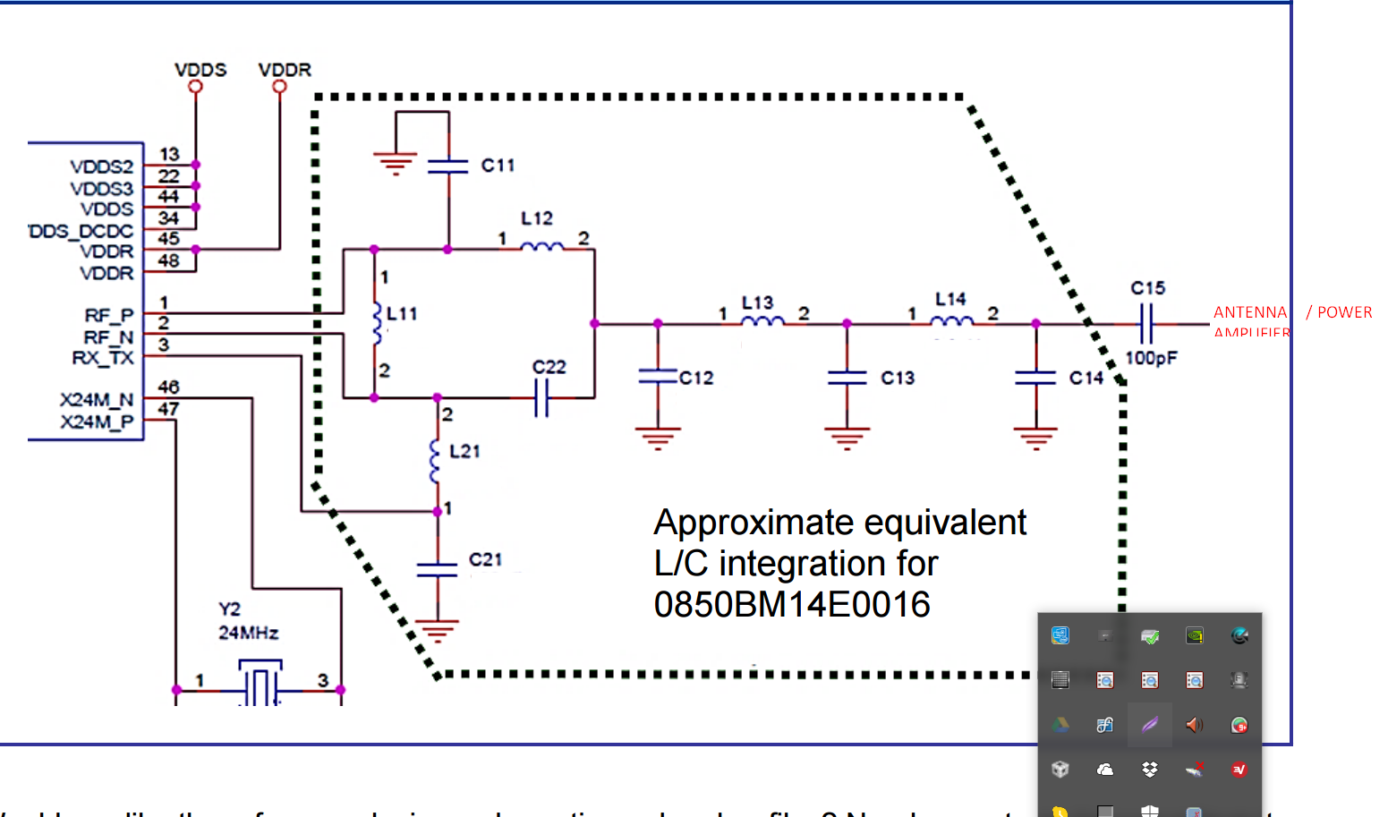
Ok - we are working on (again) design for CC1310 chipset for using higher power (per designs) with CC1310 chips.
Now we have a new ceramic filter for the CC1310 for RF frequency, etc.
So - TI - is this a needed CHIP on a board?
( )
This thread has been locked.
If you have a related question, please click the "Ask a related question" button in the top right corner. The newly created question will be automatically linked to this question.
Thanks. Yes we are using the reference de design but having a problem with the RF. This is an existing board that we added the amplifier to. My engineer came to me this am saying we need to add this other board. But I don't believe it, so trying to figure it out
Yes we used that for the first board design (14 dBm), but wanted to add the Skyworks PA to get better sending range. I'll see if I can get some data for you. Right now we are seeing if we can get these initial boards to work effectively - but my guess is that we will need to add the Baylun to make things work well in production mode. It's not clear yet. At .55c USD each it makes it worth adding to the board as a safety measure.
See the attached document for details about the design.
Everything on the board works fine except RF transmitting. If i get a new board and disconnect the PA shunt and just put an antenna on the
(forgot the name but the small rf connector on the board) than the transmit / receive works fine.
When I remove the 100pf shunt to the rf conn and put the shunt in for the PA than after 1 transmit the RF stage of the CC1310 is damaged.
After that It won't initialize anymore (gets stuck at setfrequency in easylink init).
TI TPS62063 is used as the power supply' big power and ground planes; Components selected with TI we-bench.
No disturbances in power delivery detected (checked with scope).
---
The board probably needs a redesign. I don't mind swapping out the sky-works chip for the 1190.
I have designed multiple CC1310 board before using the discrete solution. And have not had any problems other than the basic impedance matching tuning that had to be done. All those other boards worked without issue.
So we are thinking that something is up with the skyworks PA that's not making it work right. Not 100% sure. Current plan is to pull the skyworks PA off the board and switch to cc1190 as the PA. Not sure if we need to add Balun to the board design or not. Has TI tested the CC1310 with CC1190? Did they use a balun? Why is the sample design using skyworks chip instead of TI 1190 chip?
If you want since these aren't working at all I can send one to you if you wanted to check it out. It's either that or they go in the garbage.
Hi,
See attachment for CC1310 + balun + CC1190 design.
If you can spot any errors / concerns please post them here.
Thanks,
Thijsitems.zip
CC1310_LaunchPad _ 2_CC1190RF.pdfThe schematic + layout is not optimal. Try to do it more like the attached. The is for 869 MHz, 0.4 mm between the first signal layer and the ground layer
You will also need a SAW filter after the impedance matched filter-balun if you are planning to use a external PA.
//Richard
so this PDF which is 1190 -> 1101 board design from 2011 has a SAW on the board - no Balun that I can see.
It sounds like for 1190 PA + 1310 , you also need SAW + Balun to make it work? Not 100% sure why skyworks design didn't have the SAW chip in it? Was that board ever actually made?
Can we private send you our design to have it checked to see what you think?
Here's the 1190/1101 file.
Added saw filter for 915MHz; changed / added a few component values; changed pcb layout.items2.zip