This thread has been locked.

If you have a related question, please click the "Ask a related question" button in the top right corner. The newly created question will be automatically linked to this question.

CC1310: CC1310 ADC Fixed Reference test

Part Number: CC1310

Hello,

I have tested CC1310F128RHB ADC internal fixed reference with 1.44V and 4.3V with following:

-without TI-RTOS

-input signal 1VDC

-change the power supply from 3.3V to 2.0V

-CCS version: 7.4.0.00015

-SDK: simplelink_cc13x0_sdk_1_60_00_21

My Init Function is

void drvA2D_init (struct drv_adc_cfg *adcCfg)
{
    ADCBufCC26XX_Reference_Source reference;
    ADCBufCC26XX_ParamsExtension customParams;
    ADCBuf_Params adcBufParams;

    ADCBuf_init();

    /* Set up an ADCBuf peripheral in ADCBuf_RECURRENCE_MODE_CONTINUOUS */
    ADCBuf_Params_init(&adcBufParams);

    if(adcCfg->reference == drvADCRefFixed1V44)
    {
        reference = ADCBufCC26XX_FIXED_REFERENCE;
        customParams.inputScalingEnabled = false;
    }
    else if(adcCfg->reference == drvADCRefFixed4V3)
    {
        reference = ADCBufCC26XX_FIXED_REFERENCE;
        customParams.inputScalingEnabled = true;
    }
    else if(adcCfg->reference == drvADCRefVDD)
    {
        reference = ADCBufCC26XX_VDDS_REFERENCE;
        customParams.inputScalingEnabled = false;
    }

    customParams.refSource = reference;
    customParams.samplingMode = ADCBufCC26XX_SAMPING_MODE_SYNCHRONOUS;
    customParams.samplingDuration = ADCBufCC26XX_SAMPLING_DURATION_2P7_US;


    adcBufParams.custom = &customParams;
    adcBufParams.callbackFxn = (ADCBuf_Callback)adcBufCallback;
    adcBufParams.recurrenceMode = (ADCBuf_Recurrence_Mode)adcCfg->mode;
    adcBufParams.returnMode = (ADCBuf_Return_Mode)adcCfg->returnMode;
    adcBufParams.samplingFrequency = adcCfg->samplingFrequency;

    drvADCBuf = ADCBuf_open(adcCfg->adc, &adcBufParams);

    if (!drvADCBuf)
    {
        /* AdcBuf did not open correctly. */
        while(1);
    }
}

In CC1310 datasheet I sow that Typical Characteristics for ADC to VDDS are (1005 to 1006) ADC code for (1.8V to 3.8V)VDDS

But my results are following:

-with using ADCBuf_adjustRawValues() and ADCBuf_convertAdjustedToMicroVolts() functions

-witout ADCBuf_convertAdjustedToMicroVolts() function:

-without ADCBuf_adjustRawValues() and ADCBuf_convertAdjustedToMicroVolts() functions:

I attach you and the exel file with my testCC1310_ADC_TEST.xlsx

  • Hi Georgi,
    I will look into this and get back to you.
    Thanks.
  • Hi Georgi,

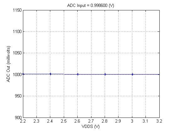
    Here is what i measured but i dont see the variation that you report. Can you describe your test setup?

    I used ADC example project from simplelink_cc13x0_sdk_1_60_00_21 and used ADCBuf_adjustRawValues() and ADCBuf_convertAdjustedToMicroVolts().

    Let me know if i am missing something that you did differently.

    Regards

  • Hello,

    it`s seems the problem is in my pin configuration. I measure between the pin and GND and I have a 45kOhm resistance, which means the pull down resistor is on. Before using this pin like analog, I was used like digital input. I`m trying to configure like input PIN_NOPULL, but still have a 45kOhm resistance. Also I try to full erase the chip, remove all gpio configuration and left only ADC driver to configure this pin and I still have 45 kOhm resistance. Do you know what I`m doing wrong in pin configuration?

    P.S.: the problem is not in pcb schematic, because we have a serial resistor before this pin, and when I remove our resistor (the pin "floating"), still have a 45 kOhm resistance.
  • Can you try the SDK example code on a different analog capable pin on your hardware?
    If you have a cc1310 launchpad i would recommend testing your code on it as well with only the ADC driver setting.

    Regards.
  • Hello,

    I found the problem. When I connect the UART to my USB UART converter (RX - IOID_13, TX - IOID_14 and GND) and if drop down the power supply from 2.8V, USB UART start to power supply the MCU throw my RX pin (IOID_13).If I continue to drop down power supply the "RX power supply" raise and for some reason, start to change ADC input channel value. Everything work well, when I disconnect USB UART converter from the PCB, ADC work stable.
    So the question now is this normal behaver for mcu or I should turn off UART before ADC start measure?

    Thanks!
  • I assume that the USB/ UART converter is powered from a separate power supply? If so I suspect that the converter contains some pull-ups that will supply the MCU though a ESD diode when VDDS drops under a given limit. Check the voltage on the RX and TX pins when you drop the voltage on VDDS and see if you are within the maximum ratings of the chip.
  • I check absolute maximum ratings and Operating supply voltage (VDDS) is between 1.8V to 3.8V. I change my power supply from ~3.6V to ~2.0V. So I did some picture of my scope to show what happen.

    Purple line - Power supply

    Yellow line - ADC input (it`s open, floating)

    Green  line - RX pin (IOID_13)

    First case: USB/UART is connected

    Second case: USB/UART is disconnect


    So if I want to use UART during ADC measure and power drops what is the property way?

    Thanks!

  • Table 5.1 in the datasheet state "voltage at any digital pin" VDDS + 0.3 V. If I read the plot correctly, you have VDDS + 1 V on the RX pin => You are outside spec on the chip.