This thread has been locked.

If you have a related question, please click the "Ask a related question" button in the top right corner. The newly created question will be automatically linked to this question.

CC1350: CC1350 RF Design and PCB Antenna 'Request for Comments'

Part Number: CC1350

Following up on my previous question now that I have my first boards back. 

Initial BLE testing shows that connectivity is very spotty/intermittent and drops frequently.  Connections can only be made when the tablet or phone is very close to the antenna.  Typically 1" or less.  When the tablet or phone is moved farther away, the connections drops and will not reconnect until the tablet or phone is brought back to being less than 1" away from the antenna.

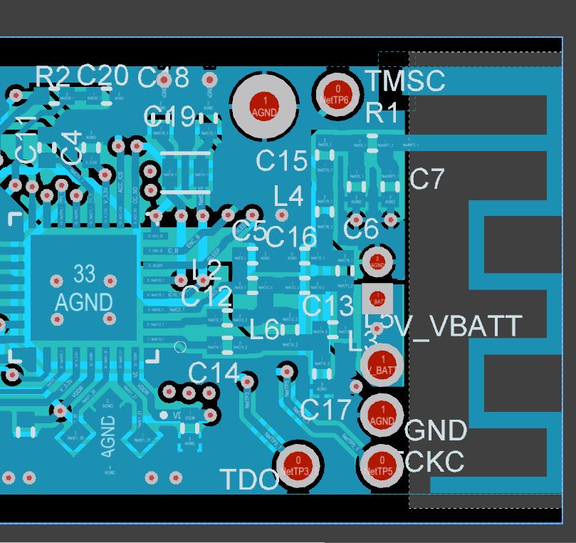
As part of the troubleshooting, I discovered an error in the antenna layout.  I removed the ground tie on the short leg of the antenna (as shown in the layout screen shot below).  When I add a white wire tie to a nearby ground test point, performance does not change.

Two other observations in my design when I go back and compare it to the AN043 reference design I pulled the antenna from:

My board is a 6 layer 0.031" board.  The AN043 board is a 4 layer 1mm (0.039") thickness.

My board house says the stackup has a dielectric constant of 4.34 at 2GHz while the AN043 calls out a dielectric constant of 4.5

As I am playing catchup in my RF theory, I am not sure how significantly those two difference will impact the performance of the BLE antenna.

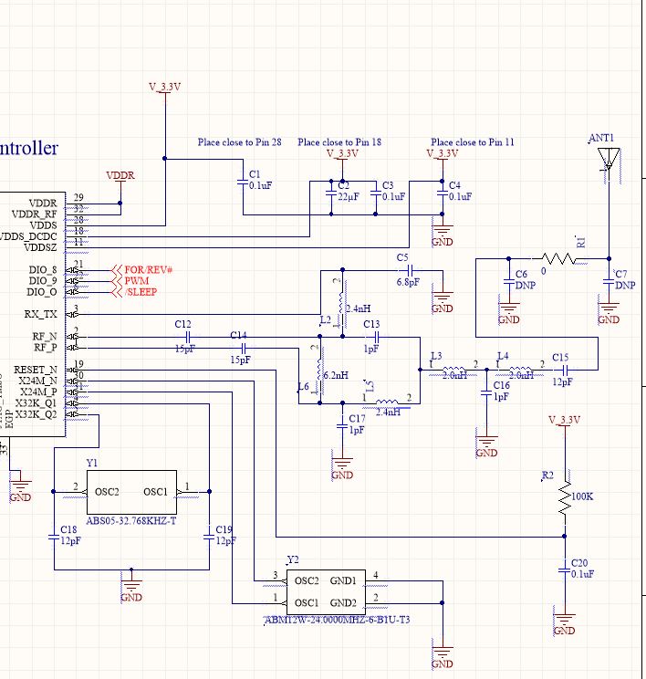
I am working to get access to a network analyzer/antenna analyzer to see if I can see what the S11 reflections look like along with any other relevant tests the folks with the equipment suggest we run.

Any thoughts or suggestions are greatly appreciated!

  • A wire to ground will have some inductance and give the antenna a different behavior.

    As a first test I would solder on a semi rigid cable and use a known good antenna on this for testing.

    Are you going to use CC1350 for BLE only and if so why?
  • I attached a 2.4HGz antenna intended for Wi-Fi/BL and retested with my simple phone/table scanner test. My range improved very slightly but not nearly as much as I need in my end product.

    I was able to get a few minutes with a VNA and that showed the resonant frequency of the antenna was ~2.6GHz. I am not sure I trust the number due to a very short warm up time on the VNA and not running a calibration before conducting the test. I am trying to schedule more time with the VNA to run additional test.

    The CC1350 was chosen very early on in the project to provide a path to low(er) frequency data transmission in future generations. In all practicality, we will end of moving to a different chip/frequency for our next generation but given the SW written for the CC1350, I am stuck with the CC1350 for now.

    Any thoughts on tuning would be appreciated.
  • Since you have access to a VNA, do you then have access to a spectrum/ signal generator enabling you to do some conducted tests?

    Since a know good antenna didn't improve things too much I would check the conducted performance before looking further into the antenna solution.