This thread has been locked.

If you have a related question, please click the "Ask a related question" button in the top right corner. The newly created question will be automatically linked to this question.

CC1310: External Attenuator Question for Japanese "Weak Power" Law Exception

Part Number: CC1310
Other Parts Discussed in Thread: , CC1350, LAUNCHXL-CC1350, CC1350STK

Hello,

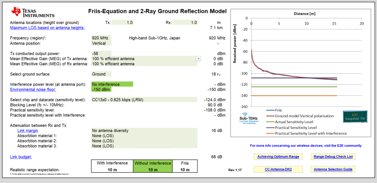
we are currently researching whether it would be possible to design a PCB (e.g. based on the many TIDA examples provided by Texas Instruments) with an external attenuator to force the output power down to -62 dBm, which if I am not mistaken should correspond to a field strength of 35uV/m (measured at 3 m). Our target frequency-band is the japanese ISM 920MHz band.

The reason behind this is the Japanese law. It states that every radiating device between 322 MHz and 10GHz shall be exempt from the need for a licence and regulation if it's radiated power is at (or below) 35uV/m (measured at 3m).

Experiments with the LAUNCHXL-CC1310 have shown that even the lowest possible setting of -10dBm would still be around 82uV/m (at 3M) which would violate the law. But if the output power could be lowered with an external attenuation circuit - without making the RX-part completely useless of course - that would make our day. (Certifying a device in Japan for "bijaku denpa" is much easier and cheaper than any other alternative.)

Now, we do not have much expertise about RF circuitry to be able answer this question so the hopes are some specialist at TI or in the community would be able to.

Additional info about the device.

- The PCB would be close to the recommended specification (e.g. a LAUNCHXL-CC1310 or similar)

- Our PCB should be small, but we rather make a bigger PCB if by doing so we can get TX/RX functionality withing 35uV/m

- The maximal distance for the packets to travel would be in average 10m (max 15m but 10m is fine) with (usually) no obstructions in between (other than a spontaneously appearing human)

- Indoor application within an public building

- Packet size and datarate are smallest possible as the device is to send brief sensor alerts only (complying to ARIB-

- Transmission only on sensor event (very infrequent)

- Requires ACK-packet from the receiver or else the sensor will re-transmit

- We already have working devices from an old series which is way too powerful.

- A PCB-trace antenna is what we wanted for the new design... But, if the requirement for 35uV/m demands a different type of antenna (ceramic SMT or external whip or dipole etc.) or even two, then so be it.

- If additional components for splitting the RX and TX paths (for separate amplification and attenuation) are required, so be it.

Would it be possible to retro-fit a ready bought off-the shelf LAUNCHXL-CC1310 with an attenuated antenna to make the above work?

Also, we have the old CC1310-modules with an SMA-antenna connector on them. Connecting two modules with a two very short RF-cable with an attenuator in between should make it possible to "simulate" on-air right? What attenuation strength would be required if the lowest settings in both CC1310 were selected?

Looking forward to hearing from you.

Best Regards

  • Hi,

    If you reduce the output power to -62 dBm which is very low, then it will be difficult to receive any data at 10 m distance even with a low data rate of 625 bps. 

    You can always modifiy the LPF on the LAUNCHXL-CC1310 to include an attenuator.

    Ref design: http://www.ti.com/general/docs/lit/getliterature.tsp?baseLiteratureNumber=swrc319&fileType=zip

    Two ways to test with 40 dB extra fixed attenuation:

    1. Use a SMA inline attenuator of 40 dB, then connect a whip antenna at P11
    2. Replace C13 & C14 with 51 ohm and replace L14 with 2700 ohm

    If the above test is unsuccessful, then I would add an LNA at the receiver and test again.

    Let us know your results.

  • Increased the output power with 6 dB to compensate the LB for a LNA on the receiver side; this is roughly 10m distance. Without the LNA, then a rough estimation would be around 5m.

    The accuracy of the range distance is very rough so you should measure this with the kits instead. 

    Link to the excel calculator: http://www.ti.com/tool/rf-range-estimator

  • Dear RGW,

    Thank you very much for the info. 

    But let me verify if I get your thinking correctly.

    At (1) you suggest to connect a 50-ohm impedance cable to P11 (JSC) at its first end, and a 40dBm attenuator screwed on the SMA on the other end of the cable, then again a whip antenna soldered to a SMA-connector to the other end of the attenuator? (I have a set of male-female attenuators which could indeed be usable in such a way)

    Also, this obviously requires to move R12 to R13, making the old R12 position DNM. Because at the moment we have only un-tampered LAUNCHpads which use the onboard PCB antenna only (which radiates really far, I was really surprised)

    For (2), exchanging C13, C14 and L14 would do the same thing as (1) ??

    (Although using plain resistors makes me feel like breaking the balanced 50-ohm antenna network somehow, but I am going to trust your expertise on this).

    Adding an LNA on the receiving LAUNCHPAD via the miniature UF.L (JSC P11) connector looks more challenging though. If an external amplifier would become required, then you suggest to do the same approach as above, i.e. using a JSC-to-SMA cable which is connected to an external LNA connected to a whip antenna?

    Do you have a recommended discrete part for the LNA? Or a suitable circuit which could be used in the custom design if required?

    (Also, how much amplification would be save to avoid accidentally frying the CC1310?)

    Also thank you for the XLS range estimator tool. Very insightful and helpful. I noticed that the setting is -56 dBm... 

    Interestingly, if set "Tx conducted output power" to -62 (the japanese are somehow very pedantic about their laws, so I would like to observe 35mV/m at  3m) and change "Link margin" to "With antenna diversity" I get 10m too (without diversity 0m).

    (SWRS181D page 45 shows an example for antenna diversity. The question is would that be a viable solution too.)

    And finally, two some 3 years ago we acquired a pair of CC1310 Evaluation Modules (for 779-930 MHz) via the discontinued product CC13xxEM-7XD-7793-4L. Instead of going the length of de-soldering parts on the LAUNCHPAD, would the above idea with the SMA-attenuator(s) be applicable for the CC13xxEM-7XD-7793-4L too? 

    The complexity here is that our system is bidirectional, i.e. the receiver MUST rend an acknowledgment back to the sender, which would require the receiver to also have an attenuator right?

    But would then the RX-part not be again attenuated over the attenuator attached?

    (Also, using the provided pulse antenna (2dBi gain) or a simple whip cable?)

    Call me amateur, but with the RX+TX requirement, is it possible to "split" the RX and TX paths, attenuate the TX path and amplify the RX path and then combine again for the CC1310?

    For the moment, do not worry about additional BOM costs, as only the final solution is more important than a few more dollars to the BOM.

    Any further help would be much appreciated.

    Best Regards

    AMK

  • Hi,

    The 40 dB fixed attenuator test should just be added onto the Tx side just to test the concept if this works and if you are able to establish a link.

    If the above concept works, then the best option would be to insert an one-bit inline attenuator such as AA104-73 32 dB from Skyworks. Then the attenuator can be activated during Tx mode (32 dB attenuation) and set to bypass in Rx mode (0.25 dB attenuation). There should be various attenuators available as well.

    AA104-73 datasheet: http://www.farnell.com/datasheets/1909041.pdf

    Alternatively,

    You can use single ended mode with one port designated to Tx and the other port designated to Rx. Then you can add a fixed resistive attenuator on the Tx side. This approach would need a SPDT switch as well.

    I would recommend Skyworks for a LNA as well and some SPDT switches have a LNA inbuilt. 

    Regards,

       Richard

  • Dear Richard,

    >> The 40 dB fixed attenuator test should just be added onto the Tx side just to test the concept if this works and if you are able to establish a link.

    I understand. I will try this first then.

    >> I would recommend Skyworks for a LNA as well and some SPDT switches have a LNA inbuilt. 

    I did some digging on the Skyworks SPDTs, but I was not able to find a SPDT with LNA for < 1GHz frequencies. There is one for 5 ~ 6 GHz though, and other manufacturers have SPDT with LNA too but only for WIFI frequencies (2.4GHz band).

    >> You can use single ended mode with one port designated to Tx and the other port designated to Rx. Then you can add a fixed resistive attenuator on the Tx side.

    That sounds like something I would surely like to try, but there is only little to no info from TI. AT first I though the CC1350 used single-ended mode, but looking at the LAUNCHXL-CC1350 in my hand I noticed an IC before the bifurcation, and looked up the design files. To my surprise it does not use a single-ended design (for 2.4Ghz and sub-1GHZ) but a Murata-DP4T (I guess a kinda differential-version of the SPDT) switch. So no ideas to take from there, I guess.

    Can you provide a reference design for a RX-TX single-ended operation, where an attenuator in the TX-path and the LNA in the RX-path could be added, for 925Mhz?

    >> This approach would need a SPDT switch as well.

    Why would that approach need a RF switch? I though the single-ended path's were (somehow) separated/stand-alone. At least it seamed to me looking at the CC1310 datasheet.

    (Agreed the datasheet says "antenna diversity" which I only know from a diversity as in "two antennas doing the same, but at different locations to improve overall performance".) 

    I was also thinking about a way more expensive solution of simply using TWO CC1310 in parallel, one for the TX path (with attenuator) and the RX-part would have the LNA,... but then I realized that the firmware would have to interconnect the two MCUs somehow, probably a real hell to make work correctly...

    Best Regards

    AMK

  • Hi,

    SPDT function with LNA from Skyworks operating range 860 to 930 MHz: SKY65378-11:

    The CC1350 STK uses two single ended ports to achieve 2.4 GHz and 868/915 MHz operation. Each port is terminated with their own pcb antenna.

    Landing page for CC1350STK: 

    The CC1350 STK 868/915 MHz port can be duplicated with one port designated for Tx and the other port for Rx. The 40 dB attenuator can be added to the Tx side. This can be done with CC1310 as well which will be the optimum option for operating just at one frequency.

    Regards,

       Richard