This thread has been locked.

If you have a related question, please click the "Ask a related question" button in the top right corner. The newly created question will be automatically linked to this question.

CC1352P: i2c slave mode not working

Part Number: CC1352P
Other Parts Discussed in Thread: CC2650, SYSCONFIG

Hi,

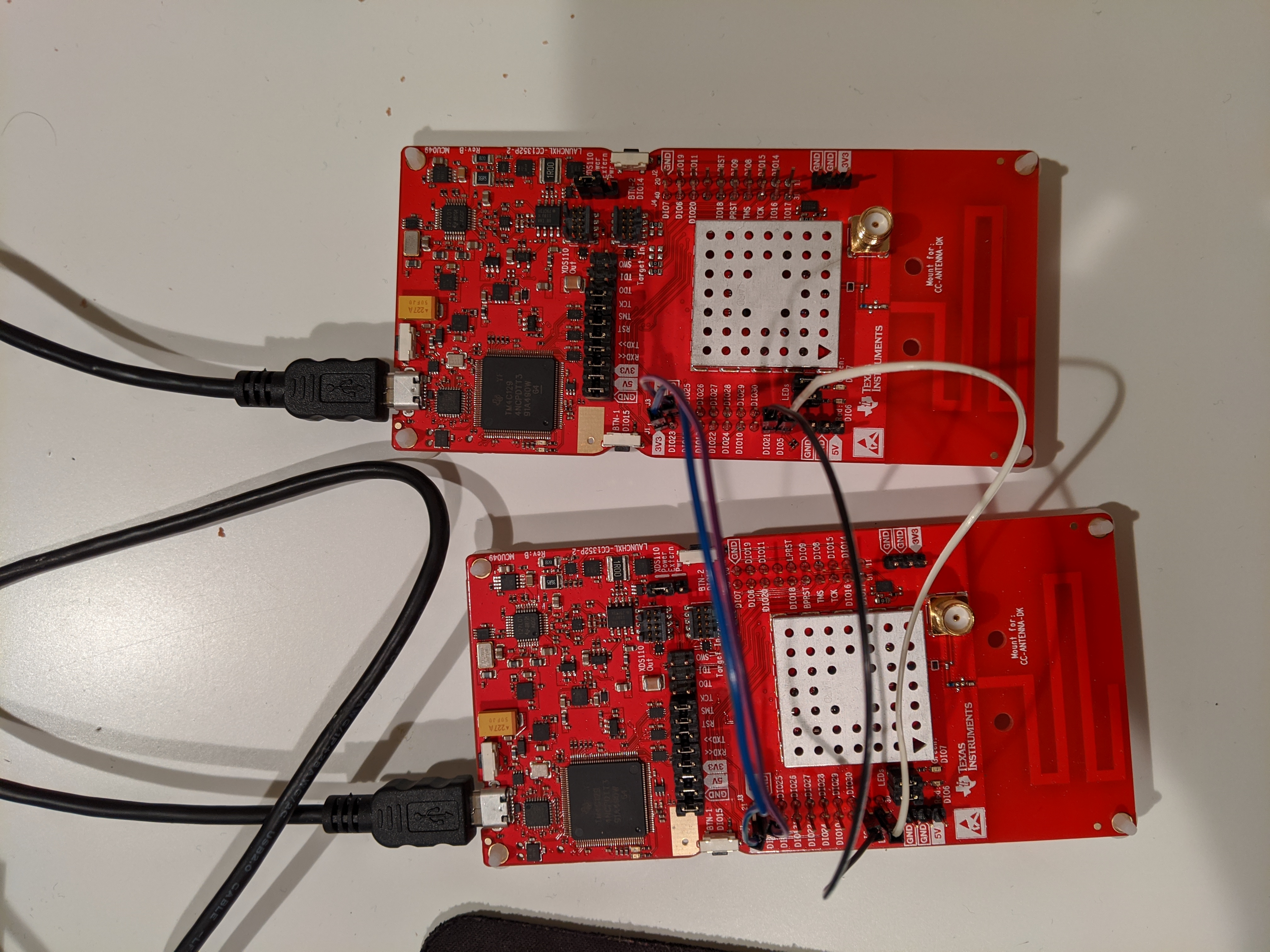
I have a setup of 2 CC1352-P2 boards which are connected by i2c (a total of four wires: Pin 21 for i2c SCL, Pin 5 for i2c SDA, and two extra: GND and 3.3v).

Following this thread: "RTOS/CC1352P: i2c slave mode" (and the code snippet in its related threads) I tried to create 2 CCS projects:

  1. First board acts as the master
  2. Second board acts as the slave

The master tries to send the slave (address 0x74) two bytes ['h', 'e'] and the slave upon receiving them sets its two LEDs (green and red).

Attached are the 2 CCS projects with the code I used.

Unfortunately it doesn't work (i.e. the slave never receives the 2 bytes message) and I'm not sure why, please advise.

Thanks,

Ofir

i2c_master.zipi2c_slave.zip

  • Hi Ofir,

    Just so I understand you correctly, have you connected 3v3 and GND between the two LaunchPads directly with wires?

  • Severin Suveren said:
    Hi Ofir,

    Just so I understand you correctly, have you connected 3v3 and GND between the two LaunchPads directly with wires?

    Correct.

    Any idea what is wrong with the code / setup?

  • Could you take a photo of the setup?

  • Below is a photo of the setup (note that in my *actual* setup I disconnected one of the USB cables below so the power of one of the board actually comes from the other board via the 3v3 pin).

    Please let me know if you need more info.

    Thanks,

    Ofir

  • From a hardware perspective it makes sense to use common ground on the two boards but disconnect the 3V3 connection since you are basically shorting the output of two voltage regulators together. 

  • Hi TER,

    Thanks for the reply, good to know.

    As I said above though: "note that in my *actual* setup I disconnected one of the USB cables below so the power of one of the board actually comes from the other board via the 3v3 pin"

    Has someone looked at the attached CCS projects (master + slave) and the code inside them?

    Thanks,

    Ofir

  • Sorry, I was only looking at the picture. When we ask about a picture, my assumption is that the picture shows the actual test setup without any exceptions. 

  • My bad =D.

    So what would be the best way to tackle this issue?

    Is there any official / (TI) internal i2c slave sample for CC1352P that we can refer to?

    I'm guessing the problem is not in the i2c master sample because this code is taken from the CCS samples.

    Thanks,

    Ofir

  • Hi Ofir,

    No sadly not, we don't have any I2C slave example. However, it should be fairly trivial to convert the normal I2C sample application into a I2C slave example. Just use the I2C driver documentation. Also, please use a debugger to check where in the code it hangs/crashes.

  • HI Severin,

    Thanks for your reply.

    I've posted it here because it is not fairly trivial at least to me and most likely to many other people due to this issue being asked in many other TI threads:

    https://e2e.ti.com/support/wireless-connectivity/sub-1-ghz/f/156/t/816289

    https://e2e.ti.com/support/legacy_forums/embedded/tirtos/f/355/t/482090

    So someone was able to test it on CC2650 but no one has ever confirmed that it works on CC1352P.

    I am stuck at the moment and I would highly appreciate more help.

    IMHO, It's not about building / merely attaching a debugger to the code, it's about debugging the protocol and/or TI-RTOS drivers/APIs that don't behave as expected.

    Note that the attached code is legit and based on samples from an official i2c TI sample for the master, and a non-official TI sample (from the forum posts) for i2c slave,

    and not something I simply made up.

    I would highly appreciate follow-up and an advice from a TI expert to look into the attached code and samples, and at least confirm whether or not the code works on CC1352P.

    Thanks,

    Ofir

  • I was able to quickly throw this together as a proof of concept for I2C slave:

    #include <stdint.h>
    #include <stddef.h>
    #include <string.h>
    #include <unistd.h>
    
    #include <ti/drivers/GPIO.h>
    #include <ti/drivers/Power.h>
    #include <ti/drivers/power/PowerCC26XX.h>
    
    #include <ti/devices/DeviceFamily.h>
    #include DeviceFamily_constructPath(driverlib/i2c.h)
    #include DeviceFamily_constructPath(driverlib/ioc.h)
    #include DeviceFamily_constructPath(inc/hw_memmap.h)
    
    #include "ti_drivers_config.h"
    
    #define Board_I2C_SCL0   IOID_4
    #define Board_I2C_SDA0   IOID_5
    
    #define I2C_SLAVE_ADDR    0x74
    
    void *mainThread(void *arg0)
    {
        Power_setDependency(PowerCC26XX_PERIPH_I2C0);
    
        IOCPinTypeI2c(I2C0_BASE, Board_I2C_SDA0, Board_I2C_SCL0);
    
        I2CSlaveInit(I2C0_BASE, I2C_SLAVE_ADDR);
    
        char i2cData[10] = { 0 };
    
        while (1)
        {
            size_t index = 0;
    
            while (I2CSlaveStatus(I2C0_BASE) != I2C_SLAVE_ACT_RREQ_FBR);
            i2cData[index] = I2CSlaveDataGet(I2C0_BASE);
    
            for (index = 1; index < 2; index++)
            {
                while (I2CSlaveStatus(I2C0_BASE) != I2C_SLAVE_ACT_RREQ);
                i2cData[index] = I2CSlaveDataGet(I2C0_BASE);
            }
    
            i2cData[index] = '\0';
    
            if (strcmp(i2cData, "he") == 0)
            {
                GPIO_toggle(CONFIG_GPIO_GLED);
            }
            else
            {
                GPIO_toggle(CONFIG_GPIO_RLED);
            }
        }
    
        return NULL;
    }

    I tested this with a normal I2C Master example, and both I2C master and slave is able to correctly complete the I2C transfer.

  • Hi Severin,

    Much appreciated the sample and the time you took to build and test it!

    I was able to build it locally, I'll test it soon and update.

    Thanks,

    Ofir

  • I configured CONFIG_GPIO_GLED and CONFIG_GPIO_RLED with SysConfig. You can replace these with the equivalent Board_GPIO_* define in your Board.h.

  • Hi Severin,

    Thank you so much, I'm able to confirm that it is working and the issue is resolved, much appreciated for the time and working sample code!

    I will mark this issue as resolved.

    Small question, the toggling of the LEDs on the board happen very fast, so I have set a breakpoint at the strcmp() of 'he' and in the slave code

    and let it resume.

    It stops at the first time but doesn't stop again (although the master.infinitely tries to send 'he' to the slave).

    Any idea?

    Thanks,

    Ofir