


Other Parts Discussed in Thread: CC-ANTENNA-DK2
Hello,
I have a question regarding Impedance Routing of the CC1352 Antenna traces. In this thread from a while ago - https://e2e.ti.com/support/wireless-connectivity/sub-1-ghz/f/156/t/842724 I have asked about the width of the tracks which were used in LAUNCHXL-CC1352P1.
The answer was:
"The trace width is 150 um for all the RF front-end routing to the "50" ohm point/switch.
Then the "CPW Ground" trace (gap/width/gap) is 500 um / 300 um / 500 um or 150 um / 250 um / 150 um. Both give approx 50 ohm characteristic impedance."
After comparison with the actual design I have a few questions which are still confusing me:
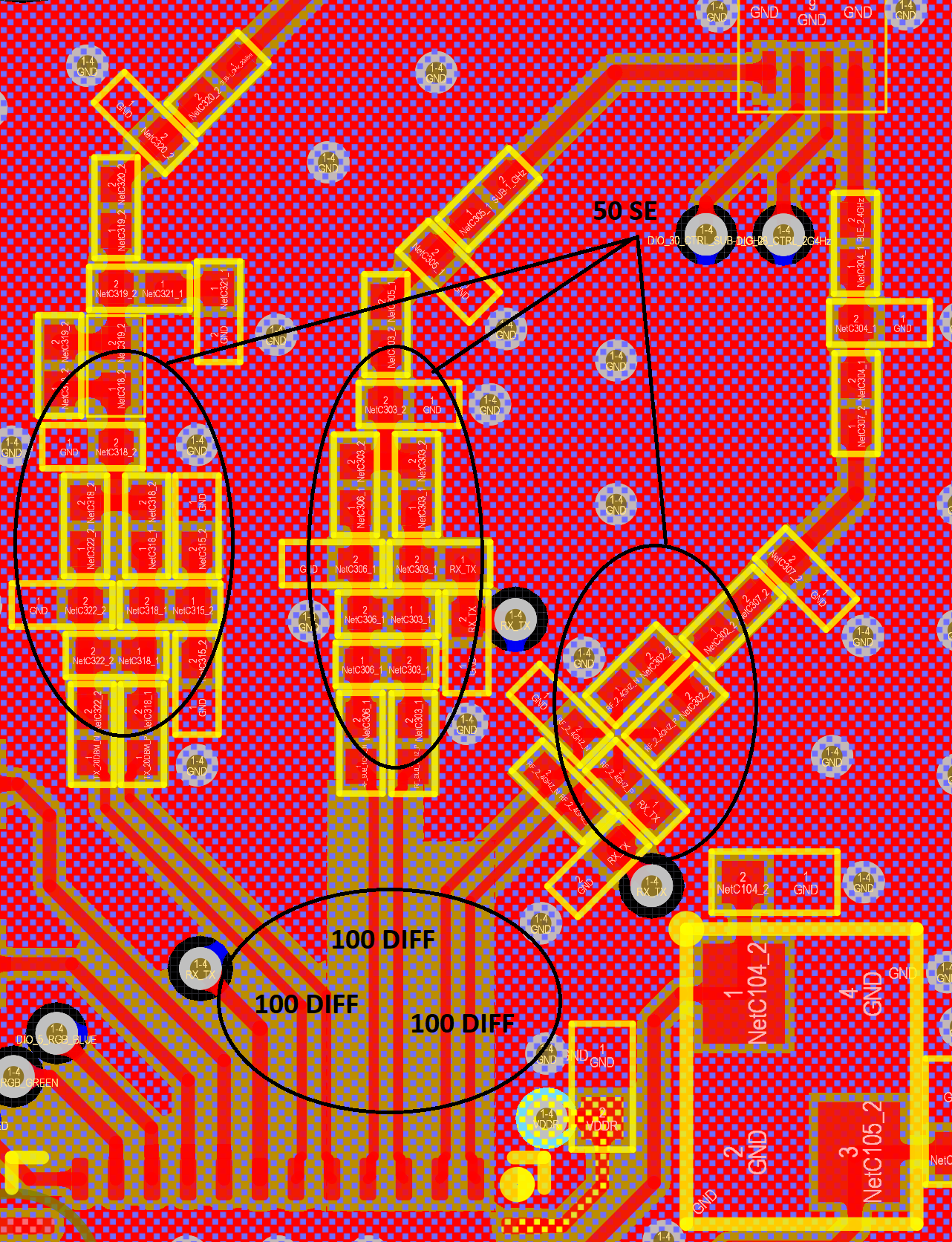
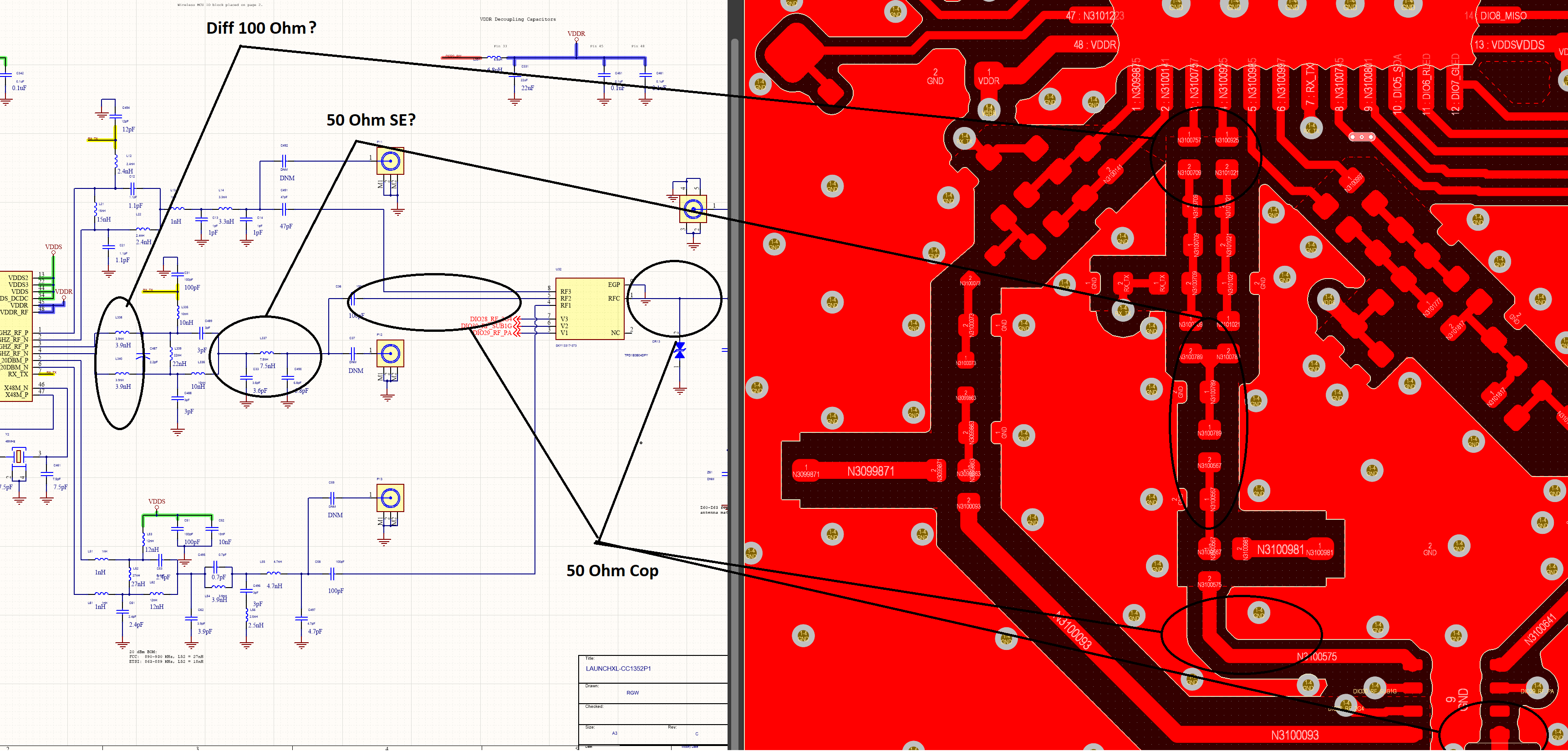
1. I assume that the routing should start with 100 Ohm Diff impedance. However, it doesn't feel like this in the Dev. Kit. design. The track width is 150um but separation varies on all ANT channels, i.e. it is not constant how it should be in diff. routing.
2. I assume that after C489, L336 the impedance should be 50 SE? (which is 150um in your stack..)
3. The track width already changes after C36 to 250um, i.e. what should be 50 Ohm Coplanar. However, at the bent point to RF SW the GND/SIG separation is not constant as well...
Does it make no difference if I route everything with 50Ohm SE?

In my design I started with 100 Ohm Differential until the MN (I also have relatively long traces until MN... ) and continued with 50 Ohm SE everywhere else until RF SW where I used 50 Ohm Coplanar. After my design came from the assembly, I then connected it through JSC to your CC-ANTENNA-DK2 Kit and the performance seems to be almost the same. So, I am a bit confused, what is the more correct approach, if I was just lucky or ..?
Thanks in advance!
Regards,
Den

