This thread has been locked.

If you have a related question, please click the "Ask a related question" button in the top right corner. The newly created question will be automatically linked to this question.

CC2652R: Questions about the oscillator of the CC2652R1 module

Part Number: CC2652R

Hi, TI expert.

My customer has a question about the oscillator of the CC2652R1 module.

In the case of the module, it is known that 48MHz for HF (High Frequency) and XOSC (32.768kHz) and RCOSC (32kHz) for LF (Low Frequency) are available.

According to the document'swra495h', it is indicated that XOSC can be used up to ±500 ppm. (Link below swra495h)

www.ti.com/.../swra495h.pdf

Currently, LF is being used by applying XOSC (32.768kHz) (2.4GHz Proprietary Mode), and a temperature related issue occurred. (Reset MCU at -20℃)

As it is an application that does not use Sleep Mode in the Power Policy, it seems that it can be applied with RCOSC (internal 32kHz), so I ask for a question.

Q1) What is the XOSC input tolerance?

What happens if the tolerance is out of bounds?

(I would like to know the allowable amplitude and frequency tolerance of the clock.)

Q2) Is there any problem with the application when using RCOSC instead of XOSC?

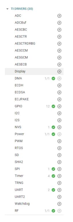
(Peripheral in use in Application-picture below)


  • Hi Grady,

    I think you'll find Fredrik's explanation in the following post helpful: 

    https://e2e.ti.com/support/wireless-connectivity/bluetooth/f/538/t/587863

    Thanks,

    Alexis

  • Why do you believe the reset at -20 degC is caused by the 32 kHz crystal oscillator?

    If your proprietary protocol does not require accurate timing using the RCOSC is not a problem.

    /F

  • Hi, Fredrikgk

    Thank you for answer.

    I contacted the customer and received the following answer.

    During the chamber test, the frequency of the 32kHz crystal of a specific module was output irregularly around -20°C, and the MCU reset phenomenon occurred during the process.

    Also, when the 32kHz crystal of the corresponding reset module was implanted into another normal module and tested, the same reset symptoms were expressed.

    Considering the above phenomenon, I think the irregular input of 32kHz Crystal is the cause of MCU reset.

  • Hi,

    We will recapitulate the CC2652R1 module oscillator inquiry.

    <Application Status>

    -"simplelink_cc13x2_26x2_sdk_3_40_00_02"-SDK(rfEchoTX / rfEchoRX) based application implementation

    -2.4GHz Proprietary / 2-GFSK used

    -WatchDog, PowerDown not used

    -FHSS implementation with Application Timer (GP Timer)

    -LF(Low Frequency) Clock Source ->'XOSC_LF' setting


    Q1) What side effects can occur when the clock input of 32.768kHz X-TAL is unstable?

    Q2) When 32.768kHz X-TAL is removed and operated with'XOSC_LF' setting, the application operates normally. Is XOSC_LF setting internally changed to RCOSC_LF?

    Please answer your questions. Thank you.

  • Hi Grady,

    Q1. I can't say exactly what happens when you use an unstable clock. We provide the specs and even have a XTAL selection guide to ensure that you can see well-defined behavior, instead of trying to debug what happens when the specs aren't followed.

    Q2. If you do not have a XTAL connected, then why use the setting that has it connected? Is it not working when the setting is changed to RCOSC_LF?

    Based off the description of the behavior seen, it sounds like they damaged the crystal during the test.

    Best,

    Nate

  • Hi Nathan

    Thank you for answer.

    The customer has additional questions below.

    ---------------------------------------------------------------------------------------------------------------------------------------------------

    - Device: CC2652R1
    - RTOS: NoRTOS
    - RF Mode: Proprietary Mode (Applies to drones, and uses 2.4GHz. Bluetooth is not used.)

    Q1) What does Initial wait Time & Retry wait Time mean?
           Not used at the application level, is it used at the core level?
          (₩simplelink_cc13x2_26x2_sdk_3_40_00_02₩source₩ti₩drivers₩power₩PowerCC26X2.h)

    Q2) Why does FW work normally when XOSC_LF(32.768kHz Crystal) is removed after setting LF(Low Frequency) to XOSC_LF?
          (SWCU185D – ‘Table 7-5’ has a choice between ‘XOSC_LF’ and ‘RCOSC_LF’. If there is no ‘XOSC_LF’ check in the Core as in Q1, will the LF setting be automatically changed to ‘RCOSC_LF’?)

    Q3) It is expected that the LF function (RTC or Power_Sleep) is not used in the current application. What is the range to which the low-spped clock (=LF, ‘XOSC_LF’ / ‘RCOSC_LF’) is applied in the CC2652R1 module?
    SWRS207F – Looking at “6.7 Timer, RTC”, it is said that RTC is used as a timer when TI-RTOS is operated. Does RTC work in NoRTOS?

    Q4) Is it reset when applying jitter to XOSC_LF? What is the jitter tolerance (Frequency Ampitude)?

    (Reset occurs when noise occurs in the clock )

    [ Normal operation ]

    [ Reset waveform when noise occurs ]

    Q5) FW RESET occurs when the XTAL part of Launchpad-CC2652R1 is touched. Is this the same phenomenon as the Q4 question? (Attachment, uartecho.c)

    When calling SysCtrlResetSourceGet(), 0x05 is returned. Is ‘RSTSRC_VDDS_LOSS -> Brown out detect on VDDS’ correct?

    What is the cause of the brown out phenomenon?

    /*
     * Copyright (c) 2015-2019, Texas Instruments Incorporated
     * All rights reserved.
     *
     * Redistribution and use in source and binary forms, with or without
     * modification, are permitted provided that the following conditions
     * are met:
     *
     * *  Redistributions of source code must retain the above copyright
     *    notice, this list of conditions and the following disclaimer.
     *
     * *  Redistributions in binary form must reproduce the above copyright
     *    notice, this list of conditions and the following disclaimer in the
     *    documentation and/or other materials provided with the distribution.
     *
     * *  Neither the name of Texas Instruments Incorporated nor the names of
     *    its contributors may be used to endorse or promote products derived
     *    from this software without specific prior written permission.
     *
     * THIS SOFTWARE IS PROVIDED BY THE COPYRIGHT HOLDERS AND CONTRIBUTORS "AS IS"
     * AND ANY EXPRESS OR IMPLIED WARRANTIES, INCLUDING, BUT NOT LIMITED TO,
     * THE IMPLIED WARRANTIES OF MERCHANTABILITY AND FITNESS FOR A PARTICULAR
     * PURPOSE ARE DISCLAIMED. IN NO EVENT SHALL THE COPYRIGHT OWNER OR
     * CONTRIBUTORS BE LIABLE FOR ANY DIRECT, INDIRECT, INCIDENTAL, SPECIAL,
     * EXEMPLARY, OR CONSEQUENTIAL DAMAGES (INCLUDING, BUT NOT LIMITED TO,
     * PROCUREMENT OF SUBSTITUTE GOODS OR SERVICES; LOSS OF USE, DATA, OR PROFITS;
     * OR BUSINESS INTERRUPTION) HOWEVER CAUSED AND ON ANY THEORY OF LIABILITY,
     * WHETHER IN CONTRACT, STRICT LIABILITY, OR TORT (INCLUDING NEGLIGENCE OR
     * OTHERWISE) ARISING IN ANY WAY OUT OF THE USE OF THIS SOFTWARE,
     * EVEN IF ADVISED OF THE POSSIBILITY OF SUCH DAMAGE.
     */
    
    /*
     *  ======== uartecho.c ========
     */
    #include <stdint.h>
    #include <stddef.h>
    #include "stdio.h"
    #include "string.h"
    #include <ti/devices/DeviceFamily.h>
    #include DeviceFamily_constructPath(driverlib/sys_ctrl.h)
    
    /* Driver Header files */
    #include <ti/drivers/GPIO.h>
    #include <ti/drivers/UART.h>
    
    /* Driver configuration */
    #include "ti_drivers_config.h"
    
    /*
     *  ======== mainThread ========
     */
        char  echoPrompt[100] = {0x00,};
    void *mainThread(void *arg0)
    {
        char        input;
        UART_Handle uart;
        UART_Params uartParams;
    
        /* Call driver init functions */
        GPIO_init();
        UART_init();
    
        /* Configure the LED pin */
        GPIO_setConfig(CONFIG_GPIO_LED_0, GPIO_CFG_OUT_STD | GPIO_CFG_OUT_LOW);
    
        /* Turn on user LED */
        GPIO_write(CONFIG_GPIO_LED_0, CONFIG_GPIO_LED_ON);
    
        /* Create a UART with data processing off. */
        UART_Params_init(&uartParams);
        uartParams.writeDataMode = UART_DATA_BINARY;
        uartParams.readDataMode = UART_DATA_BINARY;
        uartParams.readReturnMode = UART_RETURN_FULL;
        uartParams.readEcho = UART_ECHO_OFF;
        uartParams.baudRate = 115200;
    
        uart = UART_open(CONFIG_UART_0, &uartParams);
    
        if (uart == NULL) {
            /* UART_open() failed */
            while (1);
        }
    
        memset(echoPrompt, 0x00, sizeof(echoPrompt));
        sprintf(echoPrompt, "RESET Cause <SysCtrlResetSourceGet() : 0x%x >\r\n", SysCtrlResetSourceGet());
        
        UART_write(uart, echoPrompt, sizeof(echoPrompt));
    
        /* Loop forever echoing */
        while (1) {
            UART_read(uart, &input, 1);
            UART_write(uart, &input, 1);
        }
    }
    

    I have a lot of questions.

    You must be busy, but I'd appreciate it if you can answer your questions.

    Answers I'll wait.

    Thank you.

  • Q1: They're used to see how long to wait for the XTAL to stabilize (see the comments in your screenshot).

    Q2: I don't know why it seems to still work, but if you're not connecting the XTAL anyways, I would just set it on the RCOSC_LF mode to be safe.

    Q3: Refer to this thread

    Q4: We don't have a jitter tolerance listed, but the noise you're showing seems problematic. It looks like your crystal is damaged.

    Q5: Crystals are by nature very sensitive to contact. They should not be touched while the device is operating.

  • Hi, Nathan

    Thank you for answer.

    I have 2 additional questions.

    Q2) Can you think, "There is a defense code that makes it safe to operate when XTAL is removed after setting XOSC_LF in FW"?
          (Please answer in detail.)

    Q3) I do not want to implement RTC in NoRTOS environment, and I am curious if XTAL is used internally when implementing FW in NoRTOS environment.


    Please check. Answers I'll wait.

    Thank you.

  • Q2) If you want to see which clock is actually being used in operation, check the value of the AUX_DDIO_OSC:CTL0 register with the debugger when active, what is the value of SCLK_LF_SRC_SEL (maybe you can prove a snippet of the whole register)? The XTAL Oscillator will be 11, whereas the RC should be 10. I have it open on my computer now.

    Q3) The external crystal is needed to satisfy RF timing requirements regardless of the RTOS you're using. If your RF communication protocol requires synchronous timing (i.e. acknowledgement of messages sent/received...etc within a window of time) then you'll need the 32kHz XTAL. If the protocol is completely asynchronous, you will not need it. Outside of the RF, the internals on the chip do not use the external clocks at all.