This thread has been locked.
If you have a related question, please click the "Ask a related question" button in the top right corner. The newly created question will be automatically linked to this question.
Replies: 80
Views: 104500
Hi,
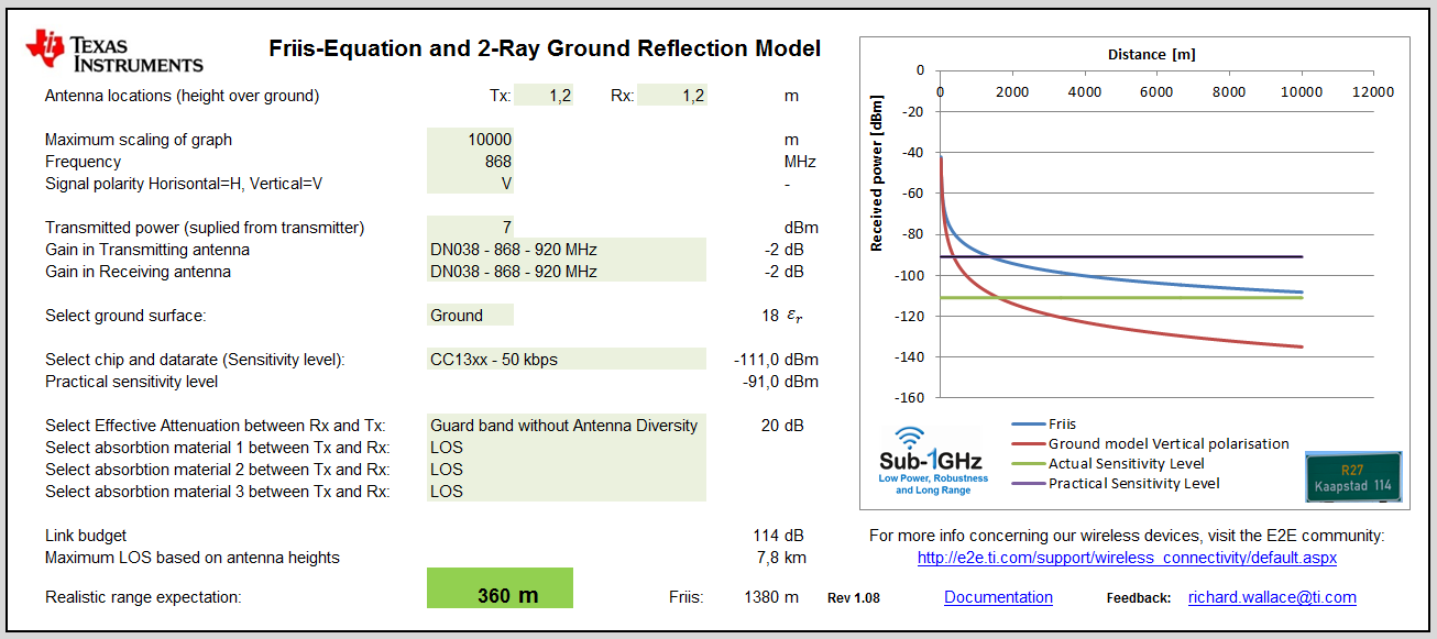
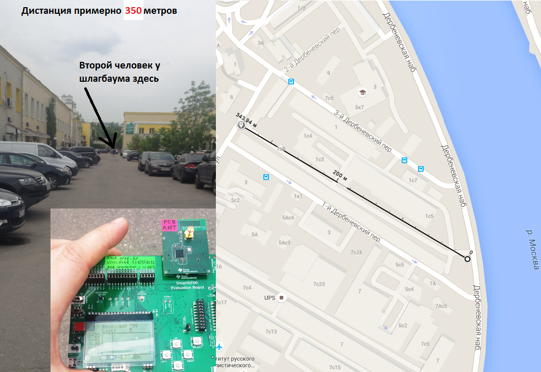
The attached excel sheet helps to estimate a practical range estimation for indoor and outdoor radio links.
This has been used a lot in TI seminars and is a helpful tool for calculating a realistic range expectation.
Latest version Rev 1.20:
SWSC002B -Range Estimation for Indoor and Outdoor Rev1_20.xlsm
and available at: http://www.ti.com/tool/rf-range-estimator
Any feedback is welcomed.
Regards, Richard
Good work Richard
What version of Excel should be used for this sheet? It seems I do not have any options to select in some cells. I use Excel 2007, macros are allowed.
Screenshot is attached.
In reply to Oleg Pushkarev:
Range Estimation for Indoor and Outdoor Rev1_06 - Excel 97-2003 version.xls
The version is Microsoft Excel 2010. Attached is an Excel 97 - 2003 version. Let me know if this solves the issues.
In reply to RGW:
there will be an app note released soon that describes all the parameters in this excel calculation. All the grey zones are input fields which can be selected via drop down menus or by just entering a value.
The fields that are shown in grey are the input fields. The heights of the Tx antenna (h1) and Rx antenna (h2) are entered at the top; for hand-held devices this is typically in the region of 1.2 m. The scaling of the graph is just for the figure scale shown on the right hand side and this is flagged in red if the scale is less than the calculated range for Friis and the ground model (2-ray). The frequency field is the operating frequency of the radio. For the signal polarity, “V” for vertical polariztion and “H” for horizontal polarization can be entered. The conducted transmitted output power should then be entered and this is normally between -20 dBm to +30 dBm pending the radio solution. The gain for the Tx antenna (GT) and Rx antenna (GR) must be entered; for a perfect matched dipole this is 2.1 dB, if this is unknown keep this value between 0 dB and 2.1 dB. There is a list of antennas which can be chosen with a recommended value for the gain; the gain in the list varies from -6 dB to +2.1 dB. The surface (εr) shown in figure 1 can be set between Ground (εr = 18), Water (εr = 88) and Sand (εr = 2.5); if this is unkown then keep this at a typcial value of 18.
For the sensitivity level of the radio, a list is available of the various radios and the data rate settings. The data rate setting is important since this determines the actual senisitivty level of the radio for a particular date rate. A larger data rate will always have a lower sensitivity level (-174 dBm + 10log10(BW) ).
Bandwidth (BW)
Theoretical sensitivity level
1 Hz
-174 dBm
1 kHz
-144 dBm
1 MHz
-114 dBm
Sensitivity level decreasing with increasing bandwidth
The list of radios with data rates supported in the excel ver1.06 release is shown in Table x. If a specific radio and data rate cannot be found then choose a setting that gives the same sensitivity level that is specified in the data sheet.
Sub-1 GHz Devices
Sensitivity level (dBm)
2.4 GHz Devices
CC11L - 0.6 kbps
-116
CC2520 - 250 kbps
-98
CC11L - 1.2 kbps
-112
CC2530 - 250 kbps
-97
CC11L - 38.2 kbps
-104
CC2538 - 250 kbps
CC11L - 250 kbps
-95
CC2540 - 1 Mbps (HG)
-93
CC11L - 500 kbps (MSK)
-90
CC2540 - 1 Mbps (Std)
-87
CC11L - 500 kbps (4-FSK)
-96
CC2541 - 250 kbps (160 kHz fdev)
CC110x - 0.6 kbps
CC2541 - 500 kbps (MSK)
-99
CC110x - 1.2 kbps
CC2541 - 1 Mbps (160 kHz fdev)
-91
CC110x - 38.2 kbps
CC2541 - 1 Mbps (250 kHz fdev)
-94
CC110x - 250 kbps
CC2541 - 2 Mbps (320 kHz fdev)
-86
CC110x - 500 kbps (MSK)
CC2541 - 2 Mbps (500 kHz fdev)
CC110x - 500 kbps (4-FSK)
CC2543 - 250 kbps (160 kHz fdev)
CC111x - 1.2 kbps
-110
CC2543 - 500 kbps (MSK)
CC111x - 38.2 kbps
-102
CC2543 - 1 Mbps (160 kHz fdev)
CC111x - 250 kbps
CC2543 - 1 Mbps (250 kHz fdev)
CC111x - 500 kbps (MSK)
CC2543 - 2 Mbps (320 kHz fdev)
CC1125 CC1190 - 0.6 kbps (LRM)
-129
CC2543 - 2 Mbps (500 kHz fdev)
CC1120 CC1190 - 0.6 kbps (LRM)
-126.5
CC2544 - 250 kbps (160 kHz fdev)
CC112x - 0.3 kbps (CG - 4 kHz fdev)
-127
CC2544 - 500 kbps (MSK)
CC112x - 1.2 kbps (4 kHz fdev)
-123
CC2544 - 1 Mbps (160 kHz fdev)
CC112x - 1.2 kbps (10 kHz fdev)
-120
CC2544 - 1 Mbps (250 kHz fdev)
CC112x - 1.2 kbps (20 kHz fdev)
-117
CC2544 - 2 Mbps (320 kHz fdev)
-84
CC112x - 4.8 kbps (OOK)
-114
CC2544 - 2 Mbps (500 kHz fdev)
-88
CC112x - 38.4 kbps (20 kHz fdev)
CC2545 - 250 kbps (160 kHz fdev)
CC112x - 50 kbps (25 kHz fdev)
CC2545 - 500 kbps (MSK)
CC112x - 200 kbps (83 kHz fdev)
-103
CC2545 - 1 Mbps (160 kHz fdev)
CC120x - 1.2 kbps (4 kHz fdev)
-122
CC2545 - 1 Mbps (250 kHz fdev)
CC120x - 4.8 kbps (OOK)
-113
CC2545 - 2 Mbps (320 kHz fdev)
CC120x - 32.768 kbps (50 kHz fdev)
-108
CC2545 - 2 Mbps (500 kHz fdev)
CC120x - 38.4 kbps (20 kHz fdev)
CC2500 - 2.4 kbps
CC120x - 50 kbps (25 kHz fdev)
-109
CC2500 - 10 kbps
CC120x - 100 kbps (50 kHz fdev)
-107
CC2500 - 250 kbps
-89
CC120x - 500 kbps (MSK)
CC2500 - 500 kbps
-83
CC120x - 1000 kbps (4-GFSK)
CC251x - 2.4 kbps
CC251x - 10 kbps
CC251x - 250 kbps
CC251x - 500 kbps
-82
Table x. Sub-1 GHz and 2.4 GHz Devices Sensitivity Levels for various data rates
The input field selection for “Select Effective Attenuation between Rx and Tx” contains a number of options which take into account the size of the guard band (link margin); and several input fields to select various construction materials normally used for indoor range prediction. The level of the guard band depends on the level of margin that is required. Theoretically, this can still be 0 dB and the radio link will still work. However, a certain guard band should be taken and this is normally in the range of 10 dB to 20 dB. For a system that requires a strong and reliable “fail safe” RF link then the margin could be increased furthermore. Similarly, for a system that can accept re-transmissions and temporary link losses then this can be reduced. With multi-path propagation effects, the signal level can vary up to 15 dB so having a guard band > 15 dB will take this into account. When not using antenna diversity then the recommended guard band is 20 dB and with antenna diversity this can be reduced to 10 dB guard band.
When calculating outdoor Line-of-Sight (LOS) range then “LOS” can be selected for the three input field options as can be seen in Figure tbd. For improved indoor range estimation, various construction materials can be chosen for the three input field options, the choice of material is shown in Table x.
Construction
Material
Attenuation (dB)
500 MHz
1 GHz
2.4 GHz
LOS
0
7" brick
3.5
5.5
7.5
8" concrete
21
25
32
1/2" drywall
0.1
0.3
0.6
1/2" glass
1.2
2.2
3.4
4" reinforced concrete
23
27
31
3" lumber
1.5
3
4.7
Table xy. Typical attenuation for various construction materials at 500 MHz, 1 GHz and 2.4 GHz
As can be seen in Table x, the material penetration is highly frequency dependent and the advantages of operating at a lower frequency is clearly seen in the link budget and range expectation. A rule-of-thumb is every 6 dB increase in a link budget doubles the range distance. To send a signal through an 8” concrete wall at 1 GHz will have approximately twice the range compared to a similar system operating at 2.4 GHz.
When all the parameters with the height of the antennas, frequency, polarization, output power, antenna gain, ground surface, sensitivity level, guard band and material between Rx & Tx; then a more realistic range can be calculated compared to the standard Friis formula.
signature
In reply to Harry: