- Ask a related questionWhat is a related question?A related question is a question created from another question. When the related question is created, it will be automatically linked to the original question.


Original question:

CC1352P: Can the 0900PC15A0036E balun be used for the CC1352P?
I'd like to verify with Texas Instruments that the CC1352P will need two baluns and a switch for the Bluetooth when using the 20dBm PA.
I plan on using the 20dBm PA for the Bluetooth (Sub GHz will not be used). For this case, will I need to use two baluns and a switch to operate the Bluetooth?
Balun for receive would connect to pins 1 & 2
Pin 1 RF_P_2_4GHZ
Pin 2 RF_N_2_4GHZ
Balun for the transmit would connect to pins 5 & 6
Pin 5 TX_20DBM_P
Pin 6 TX_20DBM_N
The switch would connect the antenna to each of the baluns.
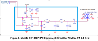
I'm planing on using the +10dBm circuit as described in the link to swra636c.pdf (and add a switch similar or the same as the SKY13317-373)
The attached image is a kludge from two schematics - Figure A-1 in the +10dBm 2.4 GHz schematic (swra636c.pdf) document and the schematic document LAUNCHXL-CC1352P1_SCHEMATIC.pdf from the swrc349a Launchpad.