Other Parts Discussed in Thread: MSP430FR5969, SYSCONFIG
hello TI team,
I'm working on SPI data transfer between MSP430FR5969 (configured as SPI Master) and LaunchXL-CC3235 (configured as SPI Slave) and facing some issues. The implementation and problem statement are as follows. Can someone please help?
Implementation:
- MSP430FR5969:
- configured as master
- SPI configuration involves clock at 1 MHz, mode 0 and eUSCI_B0 for SPI interface
- Pin 4.3 (GPIO) configured for interrupt low to high => this responds to Slave ready signal from CC3235 and carries out SPI Transmit in ISR.
- LaunchXL-CC3235:
- configured as SPI Slave
- SPI parameters are as specified in the program attached herewith.
- for this implementation, I followed below-mentioned steps:
- firstly I implemented CC3235 - CC3235 master-slave program. The one provided with the simplelink library file. The implementation worked just fine. In the same code, I carried out many modifications and with that as well, the code ran properly. Modifications I did are as follows:
- replaced all threads with FreeRTOS tasks.
- removed master ready synchronisation lines.
- changed Slave Transmit message length, message text and number of time the message is being transmitted.
- Noe, since all went well, I implemented MSP430 master SPI transfer program. This also worked fine as I could see data available on oscilloscope from MOSI pin of MSP430FR5969.
- firstly I implemented CC3235 - CC3235 master-slave program. The one provided with the simplelink library file. The implementation worked just fine. In the same code, I carried out many modifications and with that as well, the code ran properly. Modifications I did are as follows:
Problem:
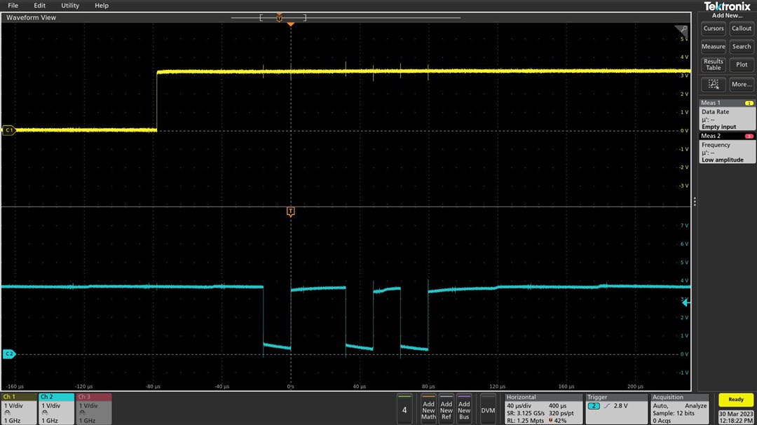
- CC3235 generates a slave ready signal on one of its GPIO. This is visible on oscilloscope.
- This slave ready signal is provided to Pin 4.3 of MSP430. Based on this signal, an interrupt gets generated and MSP430 transmits data over its MOSI pin. This is also visible on oscilloscope.
- The problem is, when CC3235 executes the command SPI_Transfer(), it then reaches to the section dmaErrorFxn. What logically should happen is, SPI_Transfer() shall either return True or False. Bus this somehow does not happen.
Can you please look at the implementation and let me know?
Please let me know if anything else is required on this from my side.
Regards,
H C Trivedi
P.S.:
- Main.c => SPI master for MSP430
- query - CC3235 Slave try 1 for Non-RTOS interface.c => SPI Slave program for CC3235
#include <msp430.h>

void clock_setup();
void port_setup();
void configure_SPI_Master();

char data1[] = {0x12, 0x24, 0x36, 0x48, 0x5A, 0x6C, 0x7E, 0x80, 0x91, 0xA3, 0xB5, 0xC7, 0xD9, 0xEB, 0x00};
unsigned char position=0;

/**
 * The recommended eUSCI initialization or reconfiguration process is:
 * Set UCSWRST
 * Initialize all eUSCI registers with UCSWRST = 1 (including UCxCTL1).
 * Configure ports.
 * Ensure that any input signals into the SPI module such as UCxSOMI (in master mode) or UCxSIMO and UCxCLK (in slave mode) have settled to their final voltage levels before clearing UCSWRST and avoid any unwanted transitions during operation.
 * Clear UCSWRST.
 * Enable interrupts (optional) with UCRXIE or UCTXIE
 */
int main(void)
{
	WDTCTL = WDTPW | WDTHOLD;	// stop watchdog timer

    // Disable the GPIO power-on default high-impedance mode to activate
    // previously configured port settings
    PM5CTL0 &= ~LOCKLPM5;

    // Configure one FRAM waitstate as required by the device datasheet for MCLK
    // operation beyond 8MHz _be                                                                                                                                                      fore_ configuring the clock system.
    // Eventhough this is directly not required here since clock operation is @ 1MHz and data transfer is at 500 kHz
    FRCTL0 = FRCTLPW | NWAITS_1;

    clock_setup();
    port_setup();
    configure_SPI_Master();

    P1IE |= BIT1;       // P1.1 interrupt enabled
    P1IES |= BIT1;      // P1.1 Hi/lo falling edge
    P1IFG &= ~BIT1;     // P1.1 IFG cleared just in case

    P4IE |= BIT3;       // P4.3 interrupt enabled
    P4IES &= ~BIT3;      // P4.3 Hi/lo falling edge
    P4IFG &= ~BIT3;     // P4.3 IFG cleared just in case

    _EINT();

	return 0;
}


void clock_setup()
{
    // Clock System Setup
    CSCTL0_H = CSKEY >> 8;                      // Unlock CS registers
    CSCTL1 = 0x0000;                            // Set DCO to 1 MHz
    CSCTL2 = 0x0033;                            // Set SMCLK = DCO = MCLK
    CSCTL3 = 0x0000;                            // no division
    CSCTL0_H = 0;                               // Lock CS registers
}


void port_setup()
{
    // Configure Pins for SPI through B0 registers.
    // following are Pins for SPI through B0 registers:

    // P1.3 Slave transmit enable
    P1SEL0 &= ~BIT3;                            // Clears P1.3 Slave Transmit Enable SEL0
    P1SEL1 |= BIT3;                             // Sets P1.3 Slave Transmit Enable SEL1

    // P2.2    SPI Clock Input (slave) / Output (master)
    P2SEL0 &= ~BIT2;                            // Clears P2.2 SPI Clock SEL0
    P2SEL1 |= BIT2;                             // Sets P2.2 SPI Clock SEL1

    // P1.6    MOSI
    P1SEL0 &= ~BIT6;                            // Clears P1.6 SIMO SEL0
    P1SEL1 |= BIT6;                             // Sets P1.6 SIMO SEL1

    // P1.7    MISO
    P1SEL0 &= ~BIT7;                            // Clears P1.7 SOMI SEL0
    P1SEL1 |= BIT7;                             // Sets P1.7 SOMI SEL1

    // port 4.3 GPIO to generate acknowledge signal for SPI Master ready indication...
    P4SEL0 &= ~BIT3;                            // Clears P4.3 for GPIO through SEL0
    P4SEL1 &= ~BIT3;                            // Clears P4.3 for GPIO through SEL1
    P4DIR &= ~BIT3;                             // sets direction as output direction

    // gets the generated SMCLK on P3.4 to verify
    P3DIR |= BIT4;
    P3SEL1 |= BIT4;                             // Output SMCLK

    P1DIR |= BIT0;                              // P1.0 output
    P1OUT &= ~BIT0;                             // P1.0 output LOW, LED Off

    P1REN |= BIT1;                              // P1.1 Enable Pullup/Pulldown
    P1OUT |= BIT1;                              // P1.1 pullup
}

void configure_SPI_Master()
{
    UCB0CTLW0 |= UCSWRST;                       // Put state machine in reset
    UCB0CTLW0 |= 0x0002;                        // STE pin is used to generate the enable signal for a 4-wire slave
    UCB0CTLW0 |= 0x0080;                        // 10b = SMCLK in master mode. Don't use in slave mode
    UCB0CTLW0 |= 0x0100;                        // 1b = Synchronous mode
    UCB0CTLW0 |= 0x0400;                        // 10b = 4-pin SPI with UCxSTE active low: Slave enabled when UCxSTE = 0
    UCB0CTLW0 |= 0x0800;                        // Master Mode
    UCB0CTLW0 |= 0x2000;                        // MSB First and 8 bit data
    UCB0CTLW0 |= 0x6000;                        // 0b = Data is changed on the first UCLK edge and captured on the following edge
                                                // 1b = The inactive state is high
    UCB0BRW = 0x0010;                           // clock rate division by 16. data transfer occurs at 500 kHz only.
    UCB0CTLW0 &= ~UCSWRST;                      // **Initialize USCI state machine**
}


#pragma vector=PORT1_VECTOR
__interrupt void Port_1(void)
{
    unsigned int i;
    for (i=0; i<5000; i++) {}                   // for software debouncing delay
    P1OUT ^= BIT0;                              // Toggle LED at P1.0
    P1IFG &= ~BIT1;                             // P1.1 IFG cleared
}

#pragma vector=PORT4_VECTOR
__interrupt void Port_4(void)
{
    P1OUT ^= BIT0;                              // Toggle LED at P1.0
    UCB0TXBUF = data1[position];
    if (position<16)
    {
        position++;
    }
    else
    {
        position = 0;
    }
    P4IFG &= ~BIT3;                             // P4.3 IFG cleared
}
/*
 *  ======== spislave.c ========
 */
#include <stddef.h>
#include <stdbool.h>
#include <stdint.h>
#include <string.h>

/* POSIX Header files */
#include <semaphore.h>
#include <unistd.h>
#include <FreeRTOS.h>

/* Driver Header files */
#include <ti/drivers/GPIO.h>
#include <ti/drivers/SPI.h>
#include <ti/display/Display.h>

/* Driver configuration */
#include "ti_drivers_config.h"

#define THREADSTACKSIZE (1024)

#define SPI_MSG_LENGTH  (1472)
#define SLAVE_MSG       ("Hello from slave, msg#: ")

#define MAX_LOOP        (1000)

unsigned char slaveRxBuffer[SPI_MSG_LENGTH];
unsigned char slaveTxBuffer[SPI_MSG_LENGTH];
unsigned long counter1 = 0;

/* Semaphore to block slave until transfer is complete */
sem_t slaveSem;

/* Status indicating whether or not SPI transfer succeeded. */
bool transferStatus;

// introducing display handle...
static Display_Handle display;

/*
 *  ======== transferCompleteFxn ========
 *  Callback function for SPI_transfer().
 */

void transferCompleteFxn(SPI_Handle handle, SPI_Transaction *transaction)
{
    // this function executes as many times as number of loop iterations..

    // printf("\n\n Entered SPI Callback function .............");
    if (transaction->status != SPI_TRANSFER_COMPLETED) {
        transferStatus = false;
    }
    else {
        transferStatus = true;
    }

    sem_post(&slaveSem);
}

// ======== slaveThread ========

void *slaveThread(void *arg0)
{
    SPI_Handle      slaveSpi;
    SPI_Params      spiParams;
    SPI_Transaction transaction;
    uint32_t        i;
    bool            transferOK;
    int32_t         status;
    char client_message[100];

    status = sem_init(&slaveSem, 0, 0);
    if (status != 0)
    {
        printf("\n Error creating slaveSem");

        while(1);
    }

    SPI_Params_init(&spiParams);
    spiParams.frameFormat = SPI_POL0_PHA0;
    spiParams.mode = SPI_SLAVE;
    spiParams.transferCallbackFxn = transferCompleteFxn;
    spiParams.transferMode = SPI_MODE_CALLBACK;
    slaveSpi = SPI_open(CONFIG_SPI_SLAVE, &spiParams);
    if (slaveSpi == NULL)
    {
        Display_printf(display, 0, 0, "\n Error initializing slave SPI");
        while (1);
    }
    else
    {
        Display_printf(display, 0, 0, "\n Slave SPI initialized");
    }

    GPIO_setConfig(CONFIG_SPI_SLAVE_READY, GPIO_CFG_OUTPUT | GPIO_CFG_OUT_LOW);
    // GPIO_setConfig(CONFIG_SPI_MASTER_READY, GPIO_CFG_INPUT);

    GPIO_write(CONFIG_SPI_SLAVE_READY, 1);
    // while (GPIO_read(CONFIG_SPI_MASTER_READY) == 0) {}

    // while (GPIO_read(CONFIG_SPI_MASTER_READY)) {}

    // Initialize slave SPI transaction structure
    memset((void *) slaveRxBuffer, 0, SPI_MSG_LENGTH);
    transaction.count = SPI_MSG_LENGTH;
    transaction.rxBuf = (void *) slaveRxBuffer;

    transferOK = SPI_transfer(slaveSpi, &transaction);
    if (transferOK)
    {
        GPIO_write(CONFIG_SPI_SLAVE_READY, 0);

        // Wait until transfer has completed
        sem_wait(&slaveSem);

        // GPIO_write(CONFIG_SPI_SLAVE_READY, 1);

        if (transferStatus == false)
        {
            printf("\n SPI transfer failed!");
        }
        else
        {
            /*if ((counter1 %100) == 0)
            {
                printf("\n Slave received: %s", slaveRxBuffer);
            }*/
            Display_printf(display, 0, 0, "Slave received: %s", slaveRxBuffer);
            // printf("\n Slave transmitted: %s", slaveTxBuffer);
            // counter1++;
        }
    }
    else
    {
        printf("\n Unsuccessful slave SPI transfer");
    }

    SPI_close(slaveSpi);

    // GPIO_setConfig(CONFIG_SPI_MASTER_READY, GPIO_CFG_OUTPUT | GPIO_CFG_OUT_LOW);
    // GPIO_write(CONFIG_SPI_SLAVE_READY, 0);

    printf("\n Done");

    while(1);

    return (NULL);
}

/*
 *  ======== mainThread ========
 */
void *mainThread(void *arg0)
{
    int                 retc;
    int                 detachState;

    /* Call driver init functions. */
    GPIO_init();
    SPI_init();
    Display_init();

    /* Open the display for output */
    display = Display_open(Display_Type_UART, NULL);
    if (display == NULL) {
        /* Failed to open display driver */
        while (1);
    }

    printf("\n Starting the SPI slave example");
    printf("\n This example requires external wires to be connected to the header pins. Please see the Readme.html and Board.html for details.");
    printf("\n\n");

    retc = xTaskCreate( slaveThread,                    // Pointer to the function that implements the task.
                        "slaveThread 1",                // Text name for the task. This is to facilitate debugging only.
                        THREADSTACKSIZE,                // Stack depth - small microcontrollers will use much less stack than this.
                        NULL,                           // This example does not use the task parameter.
                        4,                              // This task will run at Maximum priority.
                        NULL );                         // This example does not use the task handle.

    if(retc != pdPASS)
    {
        // printf("slaveThread Task Creation failed!!!");
        // printf("\n\n");
        while(1)
        {
            ;
        }
    }

    if(retc == pdPASS)
    {
        // printf("slaveThread Task Creation Succeeded !!!");
        // printf("\n\n");
    }

    while(1);

    return (NULL);
}