This thread has been locked.

If you have a related question, please click the "Ask a related question" button in the top right corner. The newly created question will be automatically linked to this question.

WL1837MOD: 2.4GHz Rx spurious emissions failure at 2nd harmonic

Part Number: WL1837MOD

Hi,

I see several other posts about this issue but none have a resolution that is working for us.

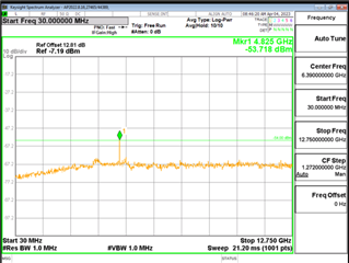
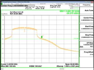
We are seeing an emission in receive mode around the 2nd harmonic for 2.4GHz WLAN at 4.825GHz that is over the -54 dBm limit.

We were using fw file wl18xx-fw-4.bin and INI file WL1837MOD_INI_FCC_CE_JP. We tried changing NumberOfAssembledAnt5 from "01" to "02" based on other posts I saw here. This brought the measurement from -52.798 dBm to -53.718, still failing.  The original ini file is below.  Please let us know what else can be tried, or any other information needed to assess. Any help would be appreciated.

Thanks in advance,

Sarah

#######################################
## WL8_1837_TI_module_INI ##
#######################################

PHY_StandAlone = 00 # Boolean Indicates that there is no MAC cortex active; One of the major impacts is that PHY needs to perform TOP init phase that is done by MAC cortex in operational Mode; 0x0 with Mac; 0x1 no Mac
PrimaryClockSettingTime = 05 # Time in millisecond from: Rising PRIMARY_CLK_REQ_OUT(9x)/CLK_REQ_OUT(5x) to valid CLK_IN_PRIMARY_P(9x)/CLK_IN_P(5x) from host
ClockValidOnWakeUp = 00 # [Not Supported] Indicate that when a host wakeup command is issued to the device a valid reference clock is already valid and stable; 0 - Reference clock is not valid (Default) 1 - Reference clock is already valid and stable (Fast Sleep)
SecondaryClockSettingTime = 05 # 189x Only; Time in millisecond from:Rising SECONDARY_CLK_REQ_OUT to valid CLK_IN_SECONDARY from host (Default 5msec).
Spare0 = 08 # [Not Supported] TI Internal Usage
AutoDetect = 00 # [Not Supported] 0x0 - Disabled; 0x1 - Enabled
Dedicated_FEM = 00 # [Not Supported] Bit 0: no FEM Bit 2..3: vendor options (0: RFMD; 1: TQS; 2: SKWS )
LowBand_component = 02 # 0x2: 2way or 3way switch. Other values N/A
LowBand_component_type = 05 # 0x5: One Hot 1.8V. Other values N/A
HighBand_component = 01 # 0x1: 2way switch. Other values N/A
HighBand_component_type = 0A # 0x9: One Hot 3V. Other values N/A
NumberOfAssembledAnt2_4 = 02 # Indicates the active bands and the number of mounted antennas for 2.4GHz;
NumberOfAssembledAnt5 = 01 # Indicates the active bands and the number of mounted antennas for 5GHz;
External_PA_DC2DC = 00 # 0: Internal_PA_DC2DC (Default); 1: External_PA_DC2DC
TCXO_LDO_Voltage = 00 # TCXO LDO 2V5 voltage level select 0x0: 2.5v; 0x1: 2.55v; 0x2: 2.6v;
XTALItrimVal = 04 # 185x Only; Current trimming for XTAL, (Default) 0x4
IO_configuration = 01 # Configure drive strength of all non-fixed IO's (Detailed in 18xx_PG2_spinner_xls_sheets.xml) according to the following table:0x0 - 8mA.0x1 - 4mA (default).0x2 - 6mA.0x3 - 2mA
SDIO_configuration = 00 # [Not Supported] Bit 0: SDIO IB Enable sync; Bit 1: SDIO IB Enable async; Bit 2: SDIO IB Enable BlockMode;
Settings = 00 # [Not Supported] TI internal - General configuration:Bit 0: N/A ;Bit 1: Enable OCLA over SoC 32K PRAM mode
RxProfile = 00 # [Not Supported] TI Internal Usage
PwrLimitReference11ABG = 55 # Single absolute output power value (dBm) that serves as the baseline for all perChanPwrLimitArrABG. Range 0..25.5dBm, Resolution 0.1dB;
PwrLimitReference11P = 64 # Single absolute output power value (dBm) that serves as the baseline for all perChanPwrLimitArr11P. Range 0..25.5dBm, Resolution 0.1dB;
Board_Type = 02 # EVB_18XX = 0; DVP_18XX = 1; HDK_18XX = 2; FPGA_18XX = 3; COM8_18XX = 4;
EnableCLPC = 00 # Boolean that enables the Closed Loop Power Control FW mechanism. In external FEM solution (only 5 GHz), we will monitor and correct the output power based on power detector readings; 0x0 Disabled; 0x1 - Enabled;
EnableTxLowPwrOnSiSoRdl = 00 # [Not Supported] TI Internal Usage
Spare1 = 00 # [Not Supported] TI Internal Usage

PerChanBoMode11ABG = 40 00 04 30 00 00 00 00 00 00 00 40 19
#PerChanBoMode11ABG represents a 2 bits per channel array (49 channels, hence 13 bytes used). Channels destribution per byte from left side is as follow:
#Byte0: 1,2,3,4; Byte1: 5,6,7,8; Byte2: 9,10,11,12; Byte3: 13,14,j1,j2; Byte4: j3,j4,j8,j12; Byte5: j16,j34,36,j38; Byte6: 40,j42,44,j46; Byte7: 48,52,56,60; Byte8: 64,100,104,108; Byte9: 112,116,120,124; Byte10: 128,132,136,140; Byte11: 149,153,157,161; Byte12: 165,spare 6 bits for fixed BO cfg
#BackOff Mode coding:
# 0 - BO taken from table per rate (default),
# 1 - Use MAX[fixed BO, Table BO] for 11n & 11g rates only and apply 200nsec TX windowing. fixed BO is set by PerChanBoMode11ABG[103:100] as follow: [103:102] - Set fixed BO for 11n & 11g in 2.4G case with static BW 20M: 0: 7dB; 1: 9dB; 2: 11dB; 3: 13dB; [101:100] - Set fixed BO for 11n & 11g in 2.4G case with static BW 40M: 0: 7dB; 1: 9dB; 2: 11dB; 3: 13dB; Note: 11b packets uses Table BO,
# 2 - Same as 1
# 3 - Use MAX[fixed BO, Table BO] for 11n, 11g & 11b rates and apply 200nsec TX windowing. fixed BO is set by PerChanBoMode11ABG[103:98] as follow: [103:102] - Set fixed BO for 11n & 11g in 2.4G case with static BW 20M: 0: 7dB; 1: 9dB; 2: 11dB; 3: 13dB; [101:100] - Set fixed BO for 11n & 11g in 2.4G case with static BW 40M: 0: 7dB; 1: 9dB; 2: 11dB; 3: 13dB; [99:98] - Set fixed BO for 11b: 0: 5dB; 1: 7dB; 2: 9dB; 3: 11dB;

PerChanBoMode11P = 00 00 00 01
#PerChanBoMode11P represents a 2 bits per channel array (14 channels, hence 4 bytes used). Channels destribution per byte from left side is as follow:
#Byte0: 171,172,173,174; Byte1: 175,176,177,178; Byte2: 179,180,181,182; Byte3: 183,184,spare 4 bits for fixed BO cfg
#BackOff Mode coding:
# 0 - BO taken from table per rate (default),
# 1 - Same as 3
# 2 - Same as 3
# 3 - Use MAX[fixed BO, Table BO] for 11n, 11a & 11p rates and apply 200nsec TX windowing. fixed BO is set by PerChanBoMode11P[31:28] as follow: [31:30] - Set fixed BO for 11n & 11g in 5G case with static BW 20M: 0: 7dB; 1: 9dB; 2: 11dB; 3: 13dB; [29:28] - Set fixed BO for 11n & 11g in 5G case with static BW 40M: 0: 7dB; 1: 9dB; 2: 11dB; 3: 13dB; Note: PerChanBoMode11P[31:28] is applicable to both 5G band and 11P band

PinMuxingPlatformOptions = 00 00 # [Not Supported] PinMux options; Byte1 185x (Bit 0: NLE, Bit 1: FM LNA EN); Byte2 189x: (Bit 0: NLE, Bit 1: GPS antenna select, Bit 2: FM LNA EN, Bit 3: GPS PPS OUT, Bit 4: GPS external LNA EN)

PerChanPwrLimitArr11P = ff ff ff ff ff ff ff
# PerChanPwrLimitArr11P Limits the TX output power at each of the 11P channels: 14 channels, 1 nibble per channel.
# PerChanPwrLimitArr11P nibbles: (ch=0),(ch=1),(ch=2),...,(ch=13).
# In each nibble: Value is in delta from the pwrLimitReferenceP(dB). Range 0dB to 15dB. Resolution: 1dB (0,1,...,15dB)

SRState = 00 # [Not Supported] Smart Reflex 0-Disabled, 1 -Enabled
SRF1 = 00 00 00 00 00 00 00 00 00 00 00 00 00 00 00 00 # [Not Supported] Smart Reflex Parameters SRF1 - 1st parameter - num of rows;
SRF2 = 00 00 00 00 00 00 00 00 00 00 00 00 00 00 00 00 # [Not Supported] Smart Reflex Parameters SRF2 - 2nd parameter - upper limit of the table;
SRF3 = 00 00 00 00 00 00 00 00 00 00 00 00 00 00 00 00 # [Not Supported] Smart Reflex Parameters SRF3 - All other parameters - Table values;


# |__CH1___|__CH2___|__CH3___|__CH4___|__CH5___|__CH6___|__CH7___|__CH8___|__CH9___|__CH10__|__CH11__|__CH12__|__CH13__|__CH14__|___j1___|___j2___|___j3___|___j4___|___j8___|__j12___|__j16___|__j34___|___36___|__j38___|___40___|__j42___|___44___|__j46___|___48___|___52___|___56___|___60___|___64___|__100___|__104___|__108___|__112___|__116___|__120___|__124___|__128___|__132___|__136___|__140___|__149___|__153___|__157___|__161___|__165___|_spare__|
PerChanPwrLimitArr11ABG = 78 88 88 78 88 88 78 88 88 78 88 88 78 88 18 78 88 88 78 88 82 78 88 88 78 88 88 78 88 88 78 88 88 78 88 88 78 88 88 FF FF FF F8 FF FF F8 FF FF F8 FF FF F8 FF FF FF FF FF FF FF FF FF FF FF FF FF FF F7 22 22 FF FF FF F7 22 22 FF FF FF F7 66 66 FF FF FF F7 66 66 F4 44 55 F4 44 55 F4 22 22 F4 22 22 F6 44 44 FF 44 44 F7 66 66 F7 66 66 F7 66 66 F7 66 66 F7 66 66 F7 66 66 F7 66 55 F7 44 55 F4 FF FF FF 33 22 FF 33 22 FF 66 66 FF 44 66 F6 FF FF FF FF FF


# PerChanPwrLimitArr11ABG Limits the TX output power at each of the 11ABG channels. 49 channels, 6 nibbles (= 3 bytes) per channel, nibble per each one of 6 modulation types at each channel.
# PerChanPwrLimitArr11ABG nibbles: (ch=0,mod=0),(ch=0,mod=1),(ch=0,mod=2),...,(ch=0,mod=5),(ch=1,mod=0),...,(ch=48,mod=5).
# In each nibble: Value is in delta from the pwrLimitReferenceABG(dB). Range is 0dB to 15dB. Resolution: 1dB (0,1,...,15dB)

PsatMode = 00 # [Not Supported] TI Internal Usage

#Following three params are For Dynamic Tx Power level control in operational mode STA HP BG only:
TxPower_level_MaxPower = ff # Max Tx power level ; (Auto mode power setting - 0xff(default mode); Manual mode power settings - 0..30dBm (Default = 0x18 = 24dbm = max power at BG1)
TxPower_level_MedPower = ff # Medium Tx power level; (Auto mode power setting - 0xff(default mode); Manual mode power settings - 0..30dBm (Default = 0x12 = 18dBm = value for optimal CC) i.e. In case of PerSubBandTxTraceLoss different from 0, TxPower_level_MedPower = 0x12dBm-PerSubBandTxTraceLoss[BG2]
TxPower_level_LowPower = ff # Low Tx power level ; (Auto mode power setting - 0xff(default mode); Manual mode power settings - 0..30dBm (Default = 0x08 = 8dBm = for best link condition)

# | BG | A Tx-1 |
# |B1|B2|A0|A1|A2|A3|A4|A5|A6|A7|
PerSubBandTxTraceLoss = 08 18 10 10 10 10 10 10 10 10
# Trace Loss value, 10 bytes (0 - BG1, 1 - BG2, 2..9 - A bands). Byte signed Value in Hex. Range -16..15.875dB, Resolution 0.125dB. This parameter is used in the TX calculations;

# | BG | A RX-1 | Reserved |
# |B1|B2|A0|A1|A2|A3|A4|A5|A6|A7| |
PerSubBandRxTraceLoss = 08 18 10 10 10 10 10 10 10 10 00 00 00 00 00 00 00 00
# Trace Loss value, 18 bytes (0 - BG1, 1 - BG2, 2..9 - RX1 A bands, 10..17 - RX2 A bands). Byte signed Value in Hex. Range -16..15.875dB, Resolution 0.125dB. This parameter is used in RX RSSI at ant point report;

TxRfMargin = 01 # Indicates the commited EVM/Mask margin in dB: 0,1,2,3 or 4. Default = 1;

TxPower_level_MaxPower_2nd = ff # For Dynamic Tx Power level control in operational mode non STA HP BG, Max Tx power level in dBm Hex val 0..30; (Default = 0x14 - max BG2)
TxPower_level_MedPower_2nd = ff # For Dynamic Tx Power level control in operational mode non STA HP BG, Medium Tx power level; (Default = 0x0A- med BG2)
TxPower_level_LowPower_2nd = ff # For Dynamic Tx Power level control in operational mode non STA HP BG, Low Tx power level; (Default = 0x05- low BG2)

  • Hi Sarah,

    Could you submit a design review here so I can take a look at the design?

  • Hey Dylan, I just sent the package for review. Looking forward to your comments.

  • Hey Sarah,

    Thank you, I will review and get back to you early next week with my feedback.

  • Thanks Dylan. I see that there is a newer FW, 8.9.1.0.0 from what we had so we are going to try that. Is there anything else you think we could try in the meantime? We are hoping to resolve this as quickly as possible, thanks again! 

    Sarah

  • Dylan,

    I'd like to add that this is conducted testing being performed for Korea compliance. 

  • Hey Sarah,

    Thanks for the info and understand on the urgency. Typically, if the INI file is up to date and the HW design is following our recommendations I wouldn't expect any issues. Therefor, I'd like to review the design to see if it uncovers anything. I'm not that familiar with Korean compliance, but I imagine its similar to FCC or RED. I'll need to double check if the limits are similar. You are currently failing on spurious emissions correct? 

  • Hey Dylan,

    Yes, spurious emissions in receive mode. The limit is -54dBm for Korea. In case it helps at all, there are several other tickets for the same issue under "Similar topics" on the right of this page, however they don't have resolutions.

  • Hey Sarah,

    Thanks for the info! Yes, I've been reviewing some of the older posts on this issue (some of which led to the FW update). I've looked over your design and nothing stands out, which I sort of expected since your are marginally failing. Would it be possible to get a capture of the conducted RSE testing? Your design matches our EVM design so I would like to compare with some of my testing (I don't have capabilities for radiated testing during this time).

    Lastly, could you try the steps below as well? I confirmed with Seong and these helped solve a previous customer issue with similar results.

    1. After connecting the EUT to RTTT and loading the FW, open LuaShell by clicking View -> LuaShell.
    2. Enter the following commands in the LuaShell window before starting the RX Spurious Emissions test:
      • ts18.API_SetAntennaMode_24G (1, 1, 0, 0, 1, 1)
      • ts18.API_ChannelTune (0, X, 3)
        • Replace X with the Channel number to test; 1, 7, or 13.
    3. Click on the RX tab on RTTT
    4. Click on "Statistics Mode" to put the device in RX mode.
  • Thanks Dylan- yes we did our best to follow the design guidelines as closely as possible :) 

    We will try the steps you suggested and let you know how it goes. Below is a capture of the failing result of our testing- let me know if you were looking for something else. The test is conducted.

    We also have an issue with one of the band edge scans for 2.4GHz. The limit is -30dBm but it measures almost 2dBm higher at -28.270. This occurs while using the global INI applied limits. We are able to pass by using sliding the power setting down to 16 in RTTT, lowering the average output down from 26.3 mW (14.2dBm) to 23.28 mW (13.67 dBm). We'd really prefer not to have to make this change and just use the original fw and global INI file as is. Can you help support this issue here as well or should I set up another thread?

    Thanks!

    Sarah

  • Hey Sarah,

    No need to make another thread if we are talking about the same hardware design.

    Unfortunately, I do think the best way to fix the issue pertaining to the band edge scan would be to manually limit the power. 

  • Hey Dylan,

    The LuaShell commands fixed the issue, thank you!   I have two remaining questions..

    1. For the spurious emission issue in Rx mode, we changed the NumberOfAssembledAnt5 from "01" to "02." Other tests were performed without this setting changed and passed.  Will changing this in our INI file affect any other settings or performance? 

    2.  For the band edge issue, adjusting the slider in RTTT down to 16 lowered the power enough to pass. I'm trying to update our INI file with this change and I don't have access to RF measurement equipment anymore to verify it so I am hoping you can give some guidance.

    I understand the PwrLimitReference11ABG is set to 0x64 or 10 dBm, and the PerChanPwrLimitArr11ABG bits per channel are added on top of that for the final output power, so to achieve an overall output power of 16, I have set that nibble to 6. My updated INI is attached.. If I load this file into RTTT will the SW reflect the new value for each channel? The value seems to remain at 30dB for all channels. Is there a way to view the INI settings in RTTT?  If not would you mind reviewing my updated INI file and letting me know if it looks like the right thing was changed?  

    Thanks again,

    Sarah

    #######################################
    ## WL8_1837_TI_module_INI ##
    #######################################

    PHY_StandAlone = 00 # Boolean Indicates that there is no MAC cortex active; One of the major impacts is that PHY needs to perform TOP init phase that is done by MAC cortex in operational Mode; 0x0 with Mac; 0x1 no Mac
    PrimaryClockSettingTime = 05 # Time in millisecond from: Rising PRIMARY_CLK_REQ_OUT(9x)/CLK_REQ_OUT(5x) to valid CLK_IN_PRIMARY_P(9x)/CLK_IN_P(5x) from host
    ClockValidOnWakeUp = 00 # [Not Supported] Indicate that when a host wakeup command is issued to the device a valid reference clock is already valid and stable; 0 - Reference clock is not valid (Default) 1 - Reference clock is already valid and stable (Fast Sleep)
    SecondaryClockSettingTime = 05 # 189x Only; Time in millisecond from:Rising SECONDARY_CLK_REQ_OUT to valid CLK_IN_SECONDARY from host (Default 5msec).
    Spare0 = 08 # [Not Supported] TI Internal Usage
    AutoDetect = 00 # [Not Supported] 0x0 - Disabled; 0x1 - Enabled
    Dedicated_FEM = 00 # [Not Supported] Bit 0: no FEM Bit 2..3: vendor options (0: RFMD; 1: TQS; 2: SKWS )
    LowBand_component = 02 # 0x2: 2way or 3way switch. Other values N/A
    LowBand_component_type = 05 # 0x5: One Hot 1.8V. Other values N/A
    HighBand_component = 01 # 0x1: 2way switch. Other values N/A
    HighBand_component_type = 0A # 0x9: One Hot 3V. Other values N/A
    NumberOfAssembledAnt2_4 = 02 # Indicates the active bands and the number of mounted antennas for 2.4GHz;
    NumberOfAssembledAnt5 = 02 # Indicates the active bands and the number of mounted antennas for 5GHz;
    External_PA_DC2DC = 00 # 0: Internal_PA_DC2DC (Default); 1: External_PA_DC2DC
    TCXO_LDO_Voltage = 00 # TCXO LDO 2V5 voltage level select 0x0: 2.5v; 0x1: 2.55v; 0x2: 2.6v;
    XTALItrimVal = 04 # 185x Only; Current trimming for XTAL, (Default) 0x4
    IO_configuration = 01 # Configure drive strength of all non-fixed IO's (Detailed in 18xx_PG2_spinner_xls_sheets.xml) according to the following table:0x0 - 8mA.0x1 - 4mA (default).0x2 - 6mA.0x3 - 2mA
    SDIO_configuration = 00 # [Not Supported] Bit 0: SDIO IB Enable sync; Bit 1: SDIO IB Enable async; Bit 2: SDIO IB Enable BlockMode;
    Settings = 00 # [Not Supported] TI internal - General configuration:Bit 0: N/A ;Bit 1: Enable OCLA over SoC 32K PRAM mode
    RxProfile = 00 # [Not Supported] TI Internal Usage
    PwrLimitReference11ABG = 55 # Single absolute output power value (dBm) that serves as the baseline for all perChanPwrLimitArrABG. Range 0..25.5dBm, Resolution 0.1dB;
    PwrLimitReference11P = 64 # Single absolute output power value (dBm) that serves as the baseline for all perChanPwrLimitArr11P. Range 0..25.5dBm, Resolution 0.1dB;
    Board_Type = 02 # EVB_18XX = 0; DVP_18XX = 1; HDK_18XX = 2; FPGA_18XX = 3; COM8_18XX = 4;
    EnableCLPC = 00 # Boolean that enables the Closed Loop Power Control FW mechanism. In external FEM solution (only 5 GHz), we will monitor and correct the output power based on power detector readings; 0x0 Disabled; 0x1 - Enabled;
    EnableTxLowPwrOnSiSoRdl = 00 # [Not Supported] TI Internal Usage
    Spare1 = 22 # [Not Supported] TI Internal Usage

    PerChanBoMode11ABG = 40 00 04 30 00 00 00 00 00 00 00 40 19
    #PerChanBoMode11ABG represents a 2 bits per channel array (49 channels, hence 13 bytes used). Channels destribution per byte from left side is as follow:
    #Byte0: 1,2,3,4; Byte1: 5,6,7,8; Byte2: 9,10,11,12; Byte3: 13,14,j1,j2; Byte4: j3,j4,j8,j12; Byte5: j16,j34,36,j38; Byte6: 40,j42,44,j46; Byte7: 48,52,56,60; Byte8: 64,100,104,108; Byte9: 112,116,120,124; Byte10: 128,132,136,140; Byte11: 149,153,157,161; Byte12: 165,spare 6 bits for fixed BO cfg
    #BackOff Mode coding:
    # 0 - BO taken from table per rate (default),
    # 1 - Use MAX[fixed BO, Table BO] for 11n & 11g rates only and apply 200nsec TX windowing. fixed BO is set by PerChanBoMode11ABG[103:100] as follow: [103:102] - Set fixed BO for 11n & 11g in 2.4G case with static BW 20M: 0: 7dB; 1: 9dB; 2: 11dB; 3: 13dB; [101:100] - Set fixed BO for 11n & 11g in 2.4G case with static BW 40M: 0: 7dB; 1: 9dB; 2: 11dB; 3: 13dB; Note: 11b packets uses Table BO,
    # 2 - Same as 1
    # 3 - Use MAX[fixed BO, Table BO] for 11n, 11g & 11b rates and apply 200nsec TX windowing. fixed BO is set by PerChanBoMode11ABG[103:98] as follow: [103:102] - Set fixed BO for 11n & 11g in 2.4G case with static BW 20M: 0: 7dB; 1: 9dB; 2: 11dB; 3: 13dB; [101:100] - Set fixed BO for 11n & 11g in 2.4G case with static BW 40M: 0: 7dB; 1: 9dB; 2: 11dB; 3: 13dB; [99:98] - Set fixed BO for 11b: 0: 5dB; 1: 7dB; 2: 9dB; 3: 11dB;

    PerChanBoMode11P = 00 00 00 01
    #PerChanBoMode11P represents a 2 bits per channel array (14 channels, hence 4 bytes used). Channels destribution per byte from left side is as follow:
    #Byte0: 171,172,173,174; Byte1: 175,176,177,178; Byte2: 179,180,181,182; Byte3: 183,184,spare 4 bits for fixed BO cfg
    #BackOff Mode coding:
    # 0 - BO taken from table per rate (default),
    # 1 - Same as 3
    # 2 - Same as 3
    # 3 - Use MAX[fixed BO, Table BO] for 11n, 11a & 11p rates and apply 200nsec TX windowing. fixed BO is set by PerChanBoMode11P[31:28] as follow: [31:30] - Set fixed BO for 11n & 11g in 5G case with static BW 20M: 0: 7dB; 1: 9dB; 2: 11dB; 3: 13dB; [29:28] - Set fixed BO for 11n & 11g in 5G case with static BW 40M: 0: 7dB; 1: 9dB; 2: 11dB; 3: 13dB; Note: PerChanBoMode11P[31:28] is applicable to both 5G band and 11P band

    PinMuxingPlatformOptions = 00 00 # [Not Supported] PinMux options; Byte1 185x (Bit 0: NLE, Bit 1: FM LNA EN); Byte2 189x: (Bit 0: NLE, Bit 1: GPS antenna select, Bit 2: FM LNA EN, Bit 3: GPS PPS OUT, Bit 4: GPS external LNA EN)

    PerChanPwrLimitArr11P = ff ff ff ff ff ff ff
    # PerChanPwrLimitArr11P Limits the TX output power at each of the 11P channels: 14 channels, 1 nibble per channel.
    # PerChanPwrLimitArr11P nibbles: (ch=0),(ch=1),(ch=2),...,(ch=13).
    # In each nibble: Value is in delta from the pwrLimitReferenceP(dB). Range 0dB to 15dB. Resolution: 1dB (0,1,...,15dB)

    SRState = 00 # [Not Supported] Smart Reflex 0-Disabled, 1 -Enabled
    SRF1 = 00 00 00 00 00 00 00 00 00 00 00 00 00 00 00 00 # [Not Supported] Smart Reflex Parameters SRF1 - 1st parameter - num of rows;
    SRF2 = 00 00 00 00 00 00 00 00 00 00 00 00 00 00 00 00 # [Not Supported] Smart Reflex Parameters SRF2 - 2nd parameter - upper limit of the table;
    SRF3 = 00 00 00 00 00 00 00 00 00 00 00 00 00 00 00 00 # [Not Supported] Smart Reflex Parameters SRF3 - All other parameters - Table values;


    # |__CH1___|__CH2___|__CH3___|__CH4___|__CH5___|__CH6___|__CH7___|__CH8___|__CH9___|__CH10__|__CH11__|__CH12__|__CH13__|__CH14__|___j1___|___j2___|___j3___|___j4___|___j8___|__j12___|__j16___|__j34___|___36___|__j38___|___40___|__j42___|___44___|__j46___|___48___|___52___|___56___|___60___|___64___|__100___|__104___|__108___|__112___|__116___|__120___|__124___|__128___|__132___|__136___|__140___|__149___|__153___|__157___|__161___|__165___|_spare__|
    PerChanPwrLimitArr11ABG = 78 88 88 78 88 88 78 88 88 78 88 88 78 88 18 78 88 88 78 88 82 78 88 88 78 88 88 78 88 88 78 88 88 78 88 88 76 88 88 FF FF FF F8 FF FF F8 FF FF F8 FF FF F8 FF FF FF FF FF FF FF FF FF FF FF FF FF FF F7 22 22 FF FF FF F7 22 22 FF FF FF F7 66 66 FF FF FF F7 66 66 F4 44 55 F4 44 55 F4 22 22 F4 22 22 F6 44 44 FF 44 44 F7 66 66 F7 66 66 F7 66 66 F7 66 66 F7 66 66 F7 66 66 F7 66 55 F7 44 55 F4 FF FF FF 33 22 FF 33 22 FF 66 66 FF 44 66 F6 FF FF FF FF FF


    # PerChanPwrLimitArr11ABG Limits the TX output power at each of the 11ABG channels. 49 channels, 6 nibbles (= 3 bytes) per channel, nibble per each one of 6 modulation types at each channel.
    # PerChanPwrLimitArr11ABG nibbles: (ch=0,mod=0),(ch=0,mod=1),(ch=0,mod=2),...,(ch=0,mod=5),(ch=1,mod=0),...,(ch=48,mod=5).
    # In each nibble: Value is in delta from the pwrLimitReferenceABG(dB). Range is 0dB to 15dB. Resolution: 1dB (0,1,...,15dB)

    PsatMode = 00 # [Not Supported] TI Internal Usage

    #Following three params are For Dynamic Tx Power level control in operational mode STA HP BG only:
    TxPower_level_MaxPower = ff # Max Tx power level ; (Auto mode power setting - 0xff(default mode); Manual mode power settings - 0..30dBm (Default = 0x18 = 24dbm = max power at BG1)
    TxPower_level_MedPower = ff # Medium Tx power level; (Auto mode power setting - 0xff(default mode); Manual mode power settings - 0..30dBm (Default = 0x12 = 18dBm = value for optimal CC) i.e. In case of PerSubBandTxTraceLoss different from 0, TxPower_level_MedPower = 0x12dBm-PerSubBandTxTraceLoss[BG2]
    TxPower_level_LowPower = ff # Low Tx power level ; (Auto mode power setting - 0xff(default mode); Manual mode power settings - 0..30dBm (Default = 0x08 = 8dBm = for best link condition)

    # | BG | A Tx-1 |
    # |B1|B2|A0|A1|A2|A3|A4|A5|A6|A7|
    PerSubBandTxTraceLoss = 08 18 10 10 10 10 10 10 10 10
    # Trace Loss value, 10 bytes (0 - BG1, 1 - BG2, 2..9 - A bands). Byte signed Value in Hex. Range -16..15.875dB, Resolution 0.125dB. This parameter is used in the TX calculations;

    # | BG | A RX-1 | Reserved |
    # |B1|B2|A0|A1|A2|A3|A4|A5|A6|A7| |
    PerSubBandRxTraceLoss = 08 18 10 10 10 10 10 10 10 10 00 00 00 00 00 00 00 00
    # Trace Loss value, 18 bytes (0 - BG1, 1 - BG2, 2..9 - RX1 A bands, 10..17 - RX2 A bands). Byte signed Value in Hex. Range -16..15.875dB, Resolution 0.125dB. This parameter is used in RX RSSI at ant point report;

    TxRfMargin = 01 # Indicates the commited EVM/Mask margin in dB: 0,1,2,3 or 4. Default = 1;

    TxPower_level_MaxPower_2nd = ff # For Dynamic Tx Power level control in operational mode non STA HP BG, Max Tx power level in dBm Hex val 0..30; (Default = 0x14 - max BG2)
    TxPower_level_MedPower_2nd = ff # For Dynamic Tx Power level control in operational mode non STA HP BG, Medium Tx power level; (Default = 0x0A- med BG2)
    TxPower_level_LowPower_2nd = ff # For Dynamic Tx Power level control in operational mode non STA HP BG, Low Tx power level; (Default = 0x05- low BG2)

  • Hey Sarah,

    Let me get double clarification on item 1 with one of my SW experts.

    For item 2, I should be able to run some tests on my EVM in the lab to confirm if those settings are being implemented correctly. I can get you this feedback by early next week if that works for you.

  • That would be great, thanks! Just for your reference- our lab saw that moving the slider down to 16 changed the average output power from 26.3 mW (14.2dBm) to 23.28 mW (13.67 dBm) and got the band edge below the -30dBm limit.

  • Hey Sarah,

    Thanks for the info! I’ll provide a progress update Monday.

  • Hi Dylan,

    Any update?

  • Hi Sarah,

    My apologies, I totally forgot I had training at the start of this week. I was able to run tests in the lab today to confirm that the setting you are adjusting is indeed limiting the power as expected (following the description in section 6 of this app note).

    Going back to your first question, there is no expectation that adjusting the NumberOfAssembledAnt5 parameter will impact any other setting or performance.

  • Dylan, 

    Great! I really appreciate you running that test since we are unable to check this ourselves. I have no more questions or issues here, thank you so much for your help!

    Take care,

    Sarah