This thread has been locked.

If you have a related question, please click the "Ask a related question" button in the top right corner. The newly created question will be automatically linked to this question.

CC3200 LaunchPad Reference design: Power management

Other Parts Discussed in Thread: CC3200

I am looking into the reference design for CC3200 launchxl and have below question on the power management section

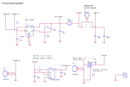
-       The design is creating 3.3V output from the LDO (VCC_LDO_3V3). This 3.3V then passes through headers to create two more signals – VCC_BRD & VBAT_CC. What are the effective voltage values of the signals VCC_BRD & VBAT_CC?

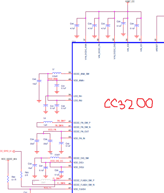
-       I see VBAT_CC is used to feed some input voltages of the CC3200 chip (pin 37, 39, 44, 54, 10). Can’t we instead just use the VCC_LDO_3V3 signal there? Do those pins need to have less than 3.3V?

-       I assume VCC_BRD is less than 3.3V, so the boost converter (U8 ) is used to output a 3.3V signal VCC_DCDC_3V3 which is then used to flash the internal memory of the CC3200 (pin 47 –VDD_FLASH). Can’t we instead use the VCC_LDO_3V3 signal to feed to the pin 47 of CC3200?

  • Hello Lilyhack,

    the VBAT-BRD and VBAT-CC are at the same voltage levels. The reason they are separated out  on the evaluation board is to be able to measure CC3200 current alone. You can see that VBAT-CC net is going to the CC3200 device  only. The voltage level  of these nets can be anywhere from 2.1V to 3.6V and hence we support a direct AA battery connection ( two AA batteries) or a regulated 3.3V option .  On the evaluation board we have used a 3.3V LDO as an example but also have a provision to power it using AA battery pack.

    The VCC-DCDC-3p3 is required ONLY for the preproduction device and should be fixed 3.3V. This supply is not required for the production device.

    Regards,

    Vivek Dham