
- Ask a related questionWhat is a related question?A related question is a question created from another question. When the related question is created, it will be automatically linked to the original question.
This thread has been locked.
If you have a related question, please click the "Ask a related question" button in the top right corner. The newly created question will be automatically linked to this question.
hi, im using cc3100 boosterpack and msp430f6736 with target board msp-TS430PZ100B
i've downloaded the SDK and ported the host driver implementation to my target board,
i'm trying to run the next program :
int main(void) {
	int AP;

    WDTCTL = WDTPW | WDTHOLD;	// Stop watchdog timer
	AP = sl_Start(0,0,0);
	return 0;
}
but it gets stuck inside the sl_start function at :
OSI_RET_OK_CHECK(sl_SyncObjWait(&g_pCB->ObjPool[pObjIdx].SyncObj, SL_OS_WAIT_FOREVER));
i've looked for solution but didnt find, what i kknow is that, the function is infinite loop, that will break only if there is interrupt from IRQ,
so i looked at P2 interrupt routine:
#pragma vector=PORT2_VECTOR
__interrupt void IntSpiGPIOHandler(void)
{
switch(__even_in_range(P2IV, P2IV_P2IFG7))
{
case P2IV_P2IFG7:
#ifndef SL_IF_TYPE_UART
if (pIraEventHandler)
{
pIraEventHandler(0);
}
#else
if(puartFlowctrl->bRtsSetByFlowControl == FALSE)
{
clear_rts();
}
#endif
break;
default:
break;
}
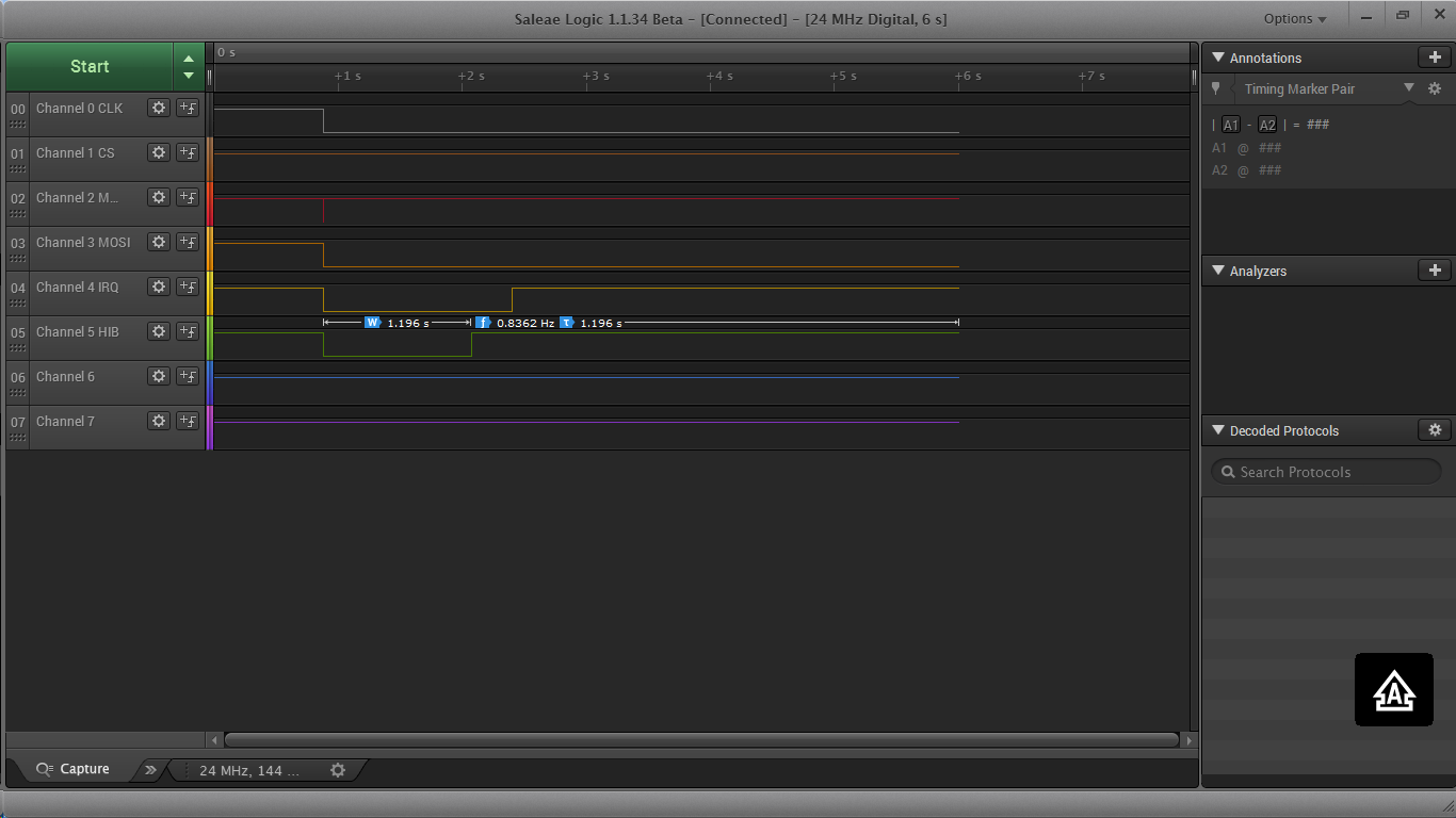
}more over i looked at the register and saw that i actually have an interrrupt at P2.7 = IRQ (P2IV = 0x10, P2IFG=0xFF, P2IE = 0x80 , P2IES = 0)
im adding also a probe on the ports and my spi.c, board.c
why doesnt it work?
/*
 * spi.c - msp430f5529 launchpad spi interface implementation
 *
 * Copyright (C) 2014 Texas Instruments Incorporated - http://www.ti.com/
 *
 *
 *  Redistribution and use in source and binary forms, with or without
 *  modification, are permitted provided that the following conditions
 *  are met:
 *
 *    Redistributions of source code must retain the above copyright
 *    notice, this list of conditions and the following disclaimer.
 *
 *    Redistributions in binary form must reproduce the above copyright
 *    notice, this list of conditions and the following disclaimer in the
 *    documentation and/or other materials provided with the
 *    distribution.
 *
 *    Neither the name of Texas Instruments Incorporated nor the names of
 *    its contributors may be used to endorse or promote products derived
 *    from this software without specific prior written permission.
 *
 *  THIS SOFTWARE IS PROVIDED BY THE COPYRIGHT HOLDERS AND CONTRIBUTORS
 *  "AS IS" AND ANY EXPRESS OR IMPLIED WARRANTIES, INCLUDING, BUT NOT
 *  LIMITED TO, THE IMPLIED WARRANTIES OF MERCHANTABILITY AND FITNESS FOR
 *  A PARTICULAR PURPOSE ARE DISCLAIMED. IN NO EVENT SHALL THE COPYRIGHT
 *  OWNER OR CONTRIBUTORS BE LIABLE FOR ANY DIRECT, INDIRECT, INCIDENTAL,
 *  SPECIAL, EXEMPLARY, OR CONSEQUENTIAL DAMAGES (INCLUDING, BUT NOT
 *  LIMITED TO, PROCUREMENT OF SUBSTITUTE GOODS OR SERVICES; LOSS OF USE,
 *  DATA, OR PROFITS; OR BUSINESS INTERRUPTION) HOWEVER CAUSED AND ON ANY
 *  THEORY OF LIABILITY, WHETHER IN CONTRACT, STRICT LIABILITY, OR TORT
 *  (INCLUDING NEGLIGENCE OR OTHERWISE) ARISING IN ANY WAY OUT OF THE USE
 *  OF THIS SOFTWARE, EVEN IF ADVISED OF THE POSSIBILITY OF SUCH DAMAGE.
 *
*/

#ifndef SL_IF_TYPE_UART
#include <msp430f6736.h>

#include "datatypes.h"
#include "simplelink.h"
#include "spi.h"
#include "board.h"

#define ASSERT_CS()          (P4OUT &= ~BIT0)
#define DEASSERT_CS()        (P4OUT |= BIT0)

int spi_Close(Fd_t fd)
{
    /* Disable WLAN Interrupt ... */
    CC3100_InterruptDisable();

    return 0;
}

Fd_t spi_Open(char *ifName, unsigned long flags)
{
    /* Select the SPI lines: MOSI/MISO on P2.3,2 CLK on P2.5 */
    // Setup P1.0 output, P1.2 UCA0SOMI, P1.3 UCA0SIMO, P1.6 UCA0CLK
    P1OUT &= ~BIT0;                               // Clear P1.0
    P1DIR |= BIT0;                                // Set P1.0 to output direction
    P1SEL |= BIT2 | BIT3 | BIT6;                  // Set P1.0,P1.2,P1.3,P1.6 to non-IO

    // Setup eUSCI_A0
    // Setup eUSCI_A0
    UCA0CTLW0 |= UCSWRST;                         // **Put state machine in reset**
    UCA0CTLW0 |= UCMST | UCMSB | UCSYNC | UCCKPH; // 3-pin, 8-bit SPI master
                                                  // Clock polarity high, MSB
    UCA0CTLW0 |= UCSSEL_2;                        // SMCLK
    UCA0BRW_L = 0x01;                             // /2
    UCA0BRW_H = 0;                                //
    UCA0MCTLW = 0;                                // No modulation
    UCA0CTLW0 &= ~UCSWRST;                        // **Initialize USCI state machine**
    UCA0IE = UCRXIE;                              // Enable USCI_A0 RX,TX interrupt


    /* P4.1 -(HIB) WLAN enable full DS */
    P4SEL &= ~BIT1;
    P4OUT &= ~BIT1;
    P4DIR |= BIT1;


    /* Configure SPI IRQ line on P2.7 */
    P2DIR &= ~BIT7;
    P2SEL &= ~BIT7;

    P2REN |= BIT7;

    /* Configure the SPI CS to be on P4.0 */
    P4OUT |= BIT0;
    P4SEL &= ~BIT0;
    P4DIR |= BIT0;

    /* 50 ms delay */
    Delay(50);

    /* Enable WLAN interrupt */
    CC3100_InterruptEnable();

    return NONOS_RET_OK;
}


int spi_Write(Fd_t fd, unsigned char *pBuff, int len)
{
        int len_to_return = len;

    ASSERT_CS();
    while (len)
    {
        while (!(UCA0IFG&UCTXIFG));
        UCA0TXBUF = *pBuff;
        while (!(UCA0IFG&UCRXIFG));
        UCA0RXBUF;
        len --;
        pBuff++;
    }

    DEASSERT_CS();

    return len_to_return;
}


int spi_Read(Fd_t fd, unsigned char *pBuff, int len)
{
    int i = 0;

    ASSERT_CS();

    for (i = 0; i < len; i ++)
    {
        while (!(UCA0IFG&UCTXIFG));
        UCA0TXBUF = 0xFF;
        while (!(UCA0IFG&UCRXIFG));
        pBuff[i] = UCA0RXBUF;
    }

    DEASSERT_CS();

    return len;
}
#endif /* SL_IF_TYPE_UART */
/*
 * board.c - msp430f5529 launchpad configuration
 *
 * Copyright (C) 2014 Texas Instruments Incorporated - http://www.ti.com/
 *
 *
 *  Redistribution and use in source and binary forms, with or without
 *  modification, are permitted provided that the following conditions
 *  are met:
 *
 *    Redistributions of source code must retain the above copyright
 *    notice, this list of conditions and the following disclaimer.
 *
 *    Redistributions in binary form must reproduce the above copyright
 *    notice, this list of conditions and the following disclaimer in the
 *    documentation and/or other materials provided with the
 *    distribution.
 *
 *    Neither the name of Texas Instruments Incorporated nor the names of
 *    its contributors may be used to endorse or promote products derived
 *    from this software without specific prior written permission.
 *
 *  THIS SOFTWARE IS PROVIDED BY THE COPYRIGHT HOLDERS AND CONTRIBUTORS
 *  "AS IS" AND ANY EXPRESS OR IMPLIED WARRANTIES, INCLUDING, BUT NOT
 *  LIMITED TO, THE IMPLIED WARRANTIES OF MERCHANTABILITY AND FITNESS FOR
 *  A PARTICULAR PURPOSE ARE DISCLAIMED. IN NO EVENT SHALL THE COPYRIGHT
 *  OWNER OR CONTRIBUTORS BE LIABLE FOR ANY DIRECT, INDIRECT, INCIDENTAL,
 *  SPECIAL, EXEMPLARY, OR CONSEQUENTIAL DAMAGES (INCLUDING, BUT NOT
 *  LIMITED TO, PROCUREMENT OF SUBSTITUTE GOODS OR SERVICES; LOSS OF USE,
 *  DATA, OR PROFITS; OR BUSINESS INTERRUPTION) HOWEVER CAUSED AND ON ANY
 *  THEORY OF LIABILITY, WHETHER IN CONTRACT, STRICT LIABILITY, OR TORT
 *  (INCLUDING NEGLIGENCE OR OTHERWISE) ARISING IN ANY WAY OUT OF THE USE
 *  OF THIS SOFTWARE, EVEN IF ADVISED OF THE POSSIBILITY OF SUCH DAMAGE.
 *
*/

#include "simplelink.h"
#include "board.h"

#define XT1_XT2_PORT_SEL            P5SEL
#define XT1_ENABLE                  (BIT4 + BIT5)
#define PMM_STATUS_ERROR  1
#define PMM_STATUS_OK     0
#define XT1HFOFFG   0

P_EVENT_HANDLER                pIraEventHandler = 0;

BOOLEAN IntIsMasked;


#ifdef SL_IF_TYPE_UART
#define ASSERT_UART(expr) {  if (!(expr)) { while(1) ;}}

unsigned char error_overrun = FALSE;
_uartFlowctrl uartFlowctrl;
_uartFlowctrl *puartFlowctrl = &uartFlowctrl;
#endif


/*!
    \brief          Increase Vcore by one level

    \param[in]      level     Level to which Vcore needs to be increased

    \return         status

    \note

       \warning
*/
static uint16_t SetVCoreUp(uint8_t level)
{
    uint16_t PMMRIE_backup, SVSMHCTL_backup, SVSMLCTL_backup;

    /*The code flow for increasing the Vcore has been altered to work around
    * the erratum FLASH37.
    * Please refer to the Errata sheet to know if a specific device is affected
    * DO NOT ALTER THIS FUNCTION */

    /* Open PMM registers for write access */
    PMMCTL0_H = 0xA5;

    /* Disable dedicated Interrupts */
    /* Backup all registers */
    PMMRIE_backup = PMMRIE;
    PMMRIE &= ~(SVMHVLRPE | SVSHPE | SVMLVLRPE | SVSLPE | SVMHVLRIE |
                    SVMHIE | SVSMHDLYIE | SVMLVLRIE | SVMLIE | SVSMLDLYIE );
    SVSMHCTL_backup = SVSMHCTL;
    SVSMLCTL_backup = SVSMLCTL;

    /* Clear flags */
    PMMIFG = 0;

    /* Set SVM highside to new level and check if a VCore increase is possible */
    SVSMHCTL = SVMHE | SVSHE | (SVSMHRRL0 * level);

    /* Wait until SVM highside is settled */
    while ((PMMIFG & SVSMHDLYIFG) == 0);

    /* Clear flag */
    PMMIFG &= ~SVSMHDLYIFG;

    /* Check if a VCore increase is possible */
    if ((PMMIFG & SVMHIFG) == SVMHIFG)
    {
        /* -> Vcc is too low for a Vcore increase */
        /* recover the previous settings */
        PMMIFG &= ~SVSMHDLYIFG;
        SVSMHCTL = SVSMHCTL_backup;

        /* Wait until SVM highside is settled */
        while ((PMMIFG & SVSMHDLYIFG) == 0);

        /* Clear all Flags */
        PMMIFG &= ~(SVMHVLRIFG | SVMHIFG | SVSMHDLYIFG | SVMLVLRIFG | SVMLIFG |
                       SVSMLDLYIFG);

        PMMRIE = PMMRIE_backup;       /* Restore PMM interrupt enable register */
        PMMCTL0_H = 0x00;             /* Lock PMM registers for write access */
        return PMM_STATUS_ERROR;      /* return: voltage not set */
    }

    /* Set also SVS highside to new level */
    /* Vcc is high enough for a Vcore increase */
    SVSMHCTL |= (SVSHRVL0 * level);

    /* Wait until SVM highside is settled */
    while ((PMMIFG & SVSMHDLYIFG) == 0);

    /* Clear flag */
    PMMIFG &= ~SVSMHDLYIFG;

    /* Set VCore to new level */
    PMMCTL0_L = PMMCOREV0 * level;

    /* Set SVM, SVS low side to new level */
    SVSMLCTL = SVMLE | (SVSMLRRL0 * level) | SVSLE | (SVSLRVL0 * level);

    /* Wait until SVM, SVS low side is settled */
    while ((PMMIFG & SVSMLDLYIFG) == 0);

    /* Clear flag */
    PMMIFG &= ~SVSMLDLYIFG;
    /*SVS, SVM core and high side are now set to protect for the new core level*/

    /* Restore Low side settings */
    /* Clear all other bits _except_ level settings */
    SVSMLCTL &= (SVSLRVL0+SVSLRVL1+SVSMLRRL0+SVSMLRRL1+SVSMLRRL2);

    /* Clear level settings in the backup register,keep all other bits */
    SVSMLCTL_backup &= ~(SVSLRVL0+SVSLRVL1+SVSMLRRL0+SVSMLRRL1+SVSMLRRL2);

    /* Restore low-side SVS monitor settings */
    SVSMLCTL |= SVSMLCTL_backup;

    /* Restore High side settings */
    /* Clear all other bits except level settings */
    SVSMHCTL &= (SVSHRVL0+SVSHRVL1+SVSMHRRL0+SVSMHRRL1+SVSMHRRL2);

    /* Clear level settings in the backup register,keep all other bits */
    SVSMHCTL_backup &= ~(SVSHRVL0+SVSHRVL1+SVSMHRRL0+SVSMHRRL1+SVSMHRRL2);

    /* Restore backup */
    SVSMHCTL |= SVSMHCTL_backup;

    /* Wait until high side, low side settled */
    while (((PMMIFG & SVSMLDLYIFG) == 0) && ((PMMIFG & SVSMHDLYIFG) == 0));

    /* Clear all Flags */
    PMMIFG &= ~(SVMHVLRIFG | SVMHIFG | SVSMHDLYIFG | SVMLVLRIFG | SVMLIFG
                    | SVSMLDLYIFG);

    PMMRIE = PMMRIE_backup;     /* Restore PMM interrupt enable register */
    PMMCTL0_H = 0x00;           /* Lock PMM registers for write access */

    return PMM_STATUS_OK;
}

/*!
    \brief Decrease Vcore by one level

    \param[in]      level     Level to which Vcore needs to be decreased

    \return         status

    \note

    \warning
*/
static uint16_t SetVCoreDown(uint8_t level)
{
    uint16_t PMMRIE_backup, SVSMHCTL_backup, SVSMLCTL_backup;

    /* The code flow for decreasing the Vcore has been altered to work around
    * the erratum FLASH37.
    * Please refer to the Errata sheet to know if a specific device is affected
    * DO NOT ALTER THIS FUNCTION */

    /* Open PMM registers for write access */
    PMMCTL0_H = 0xA5;

    /* Disable dedicated Interrupts */
    /* Backup all registers */
    PMMRIE_backup = PMMRIE;
    PMMRIE &= ~(SVMHVLRPE | SVSHPE | SVMLVLRPE | SVSLPE | SVMHVLRIE |
                       SVMHIE | SVSMHDLYIE | SVMLVLRIE | SVMLIE | SVSMLDLYIE );
    SVSMHCTL_backup = SVSMHCTL;
    SVSMLCTL_backup = SVSMLCTL;

    /* Clear flags */
    PMMIFG &= ~(SVMHIFG | SVSMHDLYIFG | SVMLIFG | SVSMLDLYIFG);

    /* Set SVM, SVS high & low side to new settings in normal mode */
    SVSMHCTL = SVMHE | (SVSMHRRL0 * level) | SVSHE | (SVSHRVL0 * level);
    SVSMLCTL = SVMLE | (SVSMLRRL0 * level) | SVSLE | (SVSLRVL0 * level);

    /* Wait until SVM high side and SVM low side is settled */
    while ((PMMIFG & SVSMHDLYIFG) == 0 || (PMMIFG & SVSMLDLYIFG) == 0);

    /* Clear flags */
    PMMIFG &= ~(SVSMHDLYIFG + SVSMLDLYIFG);
    /*SVS, SVM core and high side are now set to protect for the new core level*/

    /* Set VCore to new level */
    PMMCTL0_L = PMMCOREV0 * level;

    /* Restore Low side settings */
    /* Clear all other bits _except_ level settings */
    SVSMLCTL &= (SVSLRVL0+SVSLRVL1+SVSMLRRL0+SVSMLRRL1+SVSMLRRL2);

    /* Clear level settings in the backup register,keep all other bits */
    SVSMLCTL_backup &= ~(SVSLRVL0+SVSLRVL1+SVSMLRRL0+SVSMLRRL1+SVSMLRRL2);

    /* Restore low-side SVS monitor settings */
    SVSMLCTL |= SVSMLCTL_backup;

    /* Restore High side settings */
    /* Clear all other bits except level settings */
    SVSMHCTL &= (SVSHRVL0+SVSHRVL1+SVSMHRRL0+SVSMHRRL1+SVSMHRRL2);

    /* Clear level settings in the backup register, keep all other bits */
    SVSMHCTL_backup &= ~(SVSHRVL0+SVSHRVL1+SVSMHRRL0+SVSMHRRL1+SVSMHRRL2);

    /* Restore backup */
    SVSMHCTL |= SVSMHCTL_backup;

    /* Wait until high side, low side settled */
    while (((PMMIFG & SVSMLDLYIFG) == 0) && ((PMMIFG & SVSMHDLYIFG) == 0));

    /* Clear all Flags */
    PMMIFG &= ~(SVMHVLRIFG | SVMHIFG | SVSMHDLYIFG | SVMLVLRIFG | SVMLIFG
                    | SVSMLDLYIFG);

    PMMRIE = PMMRIE_backup;           /* Restore PMM interrupt enable register */
    PMMCTL0_H = 0x00;                 /* Lock PMM registers for write access */
    return PMM_STATUS_OK;             /* Return: OK */
}

uint16_t SetVCore(uint8_t level)
{
    uint16_t actlevel;
    uint16_t status = 0;

    level &= PMMCOREV_3;                       /* Set Mask for Max. level */
    actlevel = (PMMCTL0 & PMMCOREV_3);         /* Get actual VCore */
    /* step by step increase or decrease */
    while (((level != actlevel) && (status == 0)) || (level < actlevel))
    {
        if (level > actlevel)
        {
            status = SetVCoreUp(++actlevel);
        }
        else
        {
            status = SetVCoreDown(--actlevel);
        }
    }

    return status;
}

void LFXT_Start(uint16_t xtdrive)
{
	/*AUX3CHCTL = 0x6913;
	AUXADCCTL = 0x0000;*/

	/* If the drive setting is not already set to maximum */
    /* Set it to max for LFXT startup */
    if ((UCSCTL6 & XT1DRIVE_3)!= XT1DRIVE_3)
    {
        /* Highest drive setting for XT1startup */
        UCSCTL6_L |= XT1DRIVE1_L + XT1DRIVE0_L;
    }
    // Setup LFXT1
    UCSCTL6 &= ~(XT1OFF);                  // XT1 On
    UCSCTL6 |= XCAP_3;                     // Internal load cap

    // Loop until XT1 fault flag is cleared
    /*
    do
    {
        UCSCTL7 &= ~XT1LFOFFG;             // Clear XT1 fault flags
    } while (UCSCTL7 & XT1LFOFFG);         // Test XT1 fault flag

    */

    UCSCTL6 = (UCSCTL6 & ~(XT1DRIVE_3)) | (xtdrive); /*set requested Drive mode */
}


void Init_FLL(uint16_t fsystem, uint16_t ratio)
{
    uint16_t d, dco_div_bits;
    uint16_t mode = 0;

    /*Save actual state of FLL loop control, then disable it. This is needed to
    * prevent the FLL from acting as we are making fundamental modifications to
    * the clock setup. */
    uint16_t srRegisterState = __get_SR_register() & SCG0;
    __bic_SR_register(SCG0);

    d = ratio;
    dco_div_bits = FLLD__2;        /* Have at least a divider of 2 */

    if (fsystem > 16000)
    {
        d >>= 1 ;
        mode = 1;
    }
    else
    {
        fsystem <<= 1;               /* fsystem = fsystem * 2 */
    }

    while (d > 512)
    {
        dco_div_bits = dco_div_bits + FLLD0;  /* Set next higher div level */
        d >>= 1;
    }

    UCSCTL0 = 0x0000;              /* Set DCO to lowest Tap */

    UCSCTL2 &= ~(0x03FF);          /* Reset FN bits */
    UCSCTL2 = dco_div_bits | (d - 1);

    if (fsystem <= 630)            /*           fsystem < 0.63MHz */
        UCSCTL1 = DCORSEL_0;
    else if (fsystem <  1250)      /* 0.63MHz < fsystem < 1.25MHz */
        UCSCTL1 = DCORSEL_1;
    else if (fsystem <  2500)      /* 1.25MHz < fsystem <  2.5MHz */
        UCSCTL1 = DCORSEL_2;
    else if (fsystem <  5000)      /* 2.5MHz  < fsystem <    5MHz */
        UCSCTL1 = DCORSEL_3;
    else if (fsystem <  10000)     /* 5MHz    < fsystem <   10MHz */
        UCSCTL1 = DCORSEL_4;
    else if (fsystem <  20000)     /* 10MHz   < fsystem <   20MHz */
        UCSCTL1 = DCORSEL_5;
    else if (fsystem <  40000)     /* 20MHz   < fsystem <   40MHz */
        UCSCTL1 = DCORSEL_6;
    else
        UCSCTL1 = DCORSEL_7;

    UCSCTL7 &= ~(DCOFFG | XT1LFOFFG);
    SFRIFG1 &= ~OFIFG;
    if (mode == 1)
    {                                        /* fsystem > 16000 */
        SELECT_MCLK_SMCLK(SELM__DCOCLK + SELS__DCOCLK);     /* Select DCOCLK */
    }
    else
    {
        SELECT_MCLK_SMCLK(SELM__DCOCLKDIV + SELS__DCOCLKDIV);/*Select DCODIVCLK*/
    }

    __bis_SR_register(srRegisterState);            /* Restore previous SCG0 */
}

void Init_FLL_Settle(uint16_t fsystem, uint16_t ratio)
{
    volatile uint16_t x = ratio * 32;

    Init_FLL(fsystem, ratio);

    while (x--)
    {
        __delay_cycles(30);
    }
}


int registerInterruptHandler(P_EVENT_HANDLER InterruptHdl , void* pValue)
{
    pIraEventHandler = InterruptHdl;

    return 0;
}


void CC3100_disable()
{
    P4OUT &= ~BIT1;
}


void CC3100_enable()
{
    P4OUT |= BIT1;
}

void CC3100_InterruptEnable(void)
{
    P2IES &= ~BIT7;
    P2IE |= BIT7;

#ifdef SL_IF_TYPE_UART
    UCA0IE |= UCRXIE;
#endif

}

void CC3100_InterruptDisable()
{
    P2IE &= ~BIT7;
#ifdef SL_IF_TYPE_UART
    UCA0IE &= ~UCRXIE;
#endif
}

void MaskIntHdlr()
{
    IntIsMasked = TRUE;
}

void UnMaskIntHdlr()
{
    IntIsMasked = FALSE;
}
/*
void set_rts()
{
    P1OUT |= BIT4;
}

void clear_rts()
{
    P1OUT &= ~BIT4;
}
*/
void initClk()
{


    /* Set Vcore to accomodate for max. allowed system speed */
    SetVCore(3);
    /* Use 32.768kHz XTAL as reference */
    LFXT_Start(XT1DRIVE_0);

    /* Set system clock to max (25MHz) */
    Init_FLL_Settle(25000, 762);
    SFRIFG1 = 0;
    SFRIE1 |= OFIE;

    /* Globally enable interrupts */
    __enable_interrupt();
}

void stopWDT()
{
    WDTCTL = WDTPW + WDTHOLD;
}


#pragma vector=PORT1_VECTOR
__interrupt void Port1_ISR(void)
{
    /* Context save interrupt flag before calling interrupt vector. */
    /* Reading interrupt vector generator will automatically clear IFG flag */

    switch (__even_in_range(P1IV, P1IV_P1IFG7))
    {
        /* Vector  P1IV_NONE:  No Interrupt pending */
        case  P1IV_NONE:
            break;

        /* Vector  P1IV_P1IFG0:  P1IV P1IFG.0 */
        case  P1IV_P1IFG0:
            break;

        /* Vector  P1IV_P1IFG1:  P1IV P1IFG.1 */
        case  P1IV_P1IFG1:
            break;

        /* Vector  P1IV_P1IFG2:  P1IV P1IFG.2 */
        case  P1IV_P1IFG2:
            break;

        /* Vector  P1IV_P1IFG3:  P1IV P1IFG.3 */
        case  P1IV_P1IFG3:
            break;

        /* Vector  P1IV_P1IFG4:  P1IV P1IFG.4 */
        case  P1IV_P1IFG4:
            break;

        /* Vector  P1IV_P1IFG5:  P1IV P1IFG.5 */
        case  P1IV_P1IFG5:
            break;

        /* Vector  P1IV_P1IFG1:  P1IV P1IFG.6 */
        case  P1IV_P1IFG6:
            break;

        /* Vector  P1IV_P1IFG7:  P1IV P1IFG.7 */
        case  P1IV_P1IFG7:
            break;

        /* Default case */
        default:
            break;
    }
}

void Delay(unsigned long interval)
{
    while(interval > 0)
    {
        __delay_cycles(25000);
        interval--;
    }
}


/*!
    \brief          The IntSpiGPIOHandler interrupt handler

    \param[in]      none

    \return         none

    \note

    \warning
*/
#pragma vector=PORT2_VECTOR
__interrupt void IntSpiGPIOHandler(void)
{
    switch(__even_in_range(P2IV, P2IV_P2IFG7))
    {
      case P2IV_P2IFG7:
#ifndef SL_IF_TYPE_UART
        if (pIraEventHandler)
        {
            pIraEventHandler(0);
        }
#else
        if(puartFlowctrl->bRtsSetByFlowControl == FALSE)
        {
            clear_rts();
        }

#endif
        break;
    default:
        break;
    }
}

/*!
    \brief          The UART A0 interrupt handler

    \param[in]      none

    \return         none

    \note

    \warning
*/
#pragma vector=USCI_A0_VECTOR
__interrupt void CC3100_UART_ISR(void)
{
    switch(__even_in_range(UCA0IV,0x08))
    {
        case 0:break;                             /* Vector 0 - no interrupt */
        case 2:                                   /* Vector 2 - RXIF */
#ifdef SL_IF_TYPE_UART
        {
            UINT8 ByteRead;

            while((UCA0IFG & UCRXIFG) != 0);

            if(UCRXERR & UCA1STAT)
            {
                if(UCOE & UCA1STAT)
                {
                    error_overrun = TRUE;
                }
                ASSERT_UART(0);
            }

            ByteRead = UCA0RXBUF;

            if(puartFlowctrl->bActiveBufferIsJitterOne == TRUE)
            {
                if(puartFlowctrl->JitterBufferFreeBytes > 0)
                {
                    puartFlowctrl->JitterBuffer[puartFlowctrl->JitterBufferWriteIdx] = ByteRead;
                    puartFlowctrl->JitterBufferFreeBytes--;
                    puartFlowctrl->JitterBufferWriteIdx++;

                    if((FALSE == IntIsMasked) && (NULL != pIraEventHandler))
                    {
                        pIraEventHandler(0);
                    }
                }
                else
                {
                    if(P1OUT & BIT3)
                    {
                        ASSERT_UART(0);
                    }
                }

                if(puartFlowctrl->JitterBufferFreeBytes <= UART_READ_JITTER_RTS_GUARD)
                {
                    set_rts();
                    puartFlowctrl->bRtsSetByFlowControl = TRUE;
                }

                if(puartFlowctrl->JitterBufferWriteIdx > (UART_READ_JITTER_BUFFER_SIZE - 1))
                {
                    puartFlowctrl->JitterBufferWriteIdx = 0;
                }
            }
            else
            {
                puartFlowctrl->pActiveBuffer[puartFlowctrl->ActiveBufferWriteCounter++] = ByteRead;
            }
        }
#endif
            break;
        case 4:break;                             /* Vector 4 - TXIFG */
        default: break;
    }
}

hi
SL_IF_TYPE_UART is not defined in pre-symbol list, also i looked to see maybe it was defined at libarary but its not,
the implementation of sl_IfRegIntHdlr
int registerInterruptHandler(P_EVENT_HANDLER InterruptHdl , void* pValue)
{
    pIraEventHandler = InterruptHdl;

    return 0;
}

opened pIraEventHandler :
P_EVENT_HANDLER pIraEventHandler = 0;
and the definition of P_EVENT_HANDLER :
typedef void (*P_EVENT_HANDLER)(void* pValue);
i did put a break point in the IntSpiGPIOHandler before i was posting, the program dont gets there
im adding the sl_start implementation :
#if _SL_INCLUDE_FUNC(sl_Start)
int sl_Start(const void* pIfHdl, char* pDevName, const P_INIT_CALLBACK pInitCallBack)
{
    int pObjIdx = MAX_CONCURRENT_ACTIONS;
    InitComplete_t  AsyncRsp;

    /* callback init */
    _SlDrvDriverCBInit();

    /* open the interface: usually SPI or UART */
    if (NULL == pIfHdl)
    {
        g_pCB->FD = sl_IfOpen(pDevName, 0);
    }
    else
    {
        g_pCB->FD = (_SlFd_t)pIfHdl;
    }
    /* Use Obj to issue the command, if not available try later */
    pObjIdx = _SlDrvWaitForPoolObj(START_STOP_ID,SL_MAX_SOCKETS);
    if (MAX_CONCURRENT_ACTIONS == pObjIdx)
    {
         return SL_POOL_IS_EMPTY;
    }
    OSI_RET_OK_CHECK(sl_LockObjLock(&g_pCB->ProtectionLockObj, SL_OS_WAIT_FOREVER));
    g_pCB->ObjPool[pObjIdx].pRespArgs = (UINT8 *)&AsyncRsp;
    OSI_RET_OK_CHECK(sl_LockObjUnlock(&g_pCB->ProtectionLockObj));

    if( g_pCB->FD >= 0)
    {
        sl_DeviceDisable();

        sl_IfRegIntHdlr((SL_P_EVENT_HANDLER)_SlDrvRxIrqHandler, NULL);

        sl_DeviceEnable();

        if (NULL != pInitCallBack)
        {
            g_pCB->pInitCallback = pInitCallBack;
        }
        else
        {
			OSI_RET_OK_CHECK(sl_SyncObjWait(&g_pCB->ObjPool[pObjIdx].SyncObj, SL_OS_WAIT_FOREVER));
	        /*release Pool Object*/
            _SlDrvReleasePoolObj(g_pCB->FunctionParams.AsyncExt.ActionIndex);
			return GetStartResponseConvert(AsyncRsp.Status);
		}
    }

    return (int)g_pCB->FD;

}
the program stucks there
the IRQ handler:
/*****************************************************************************
 _SlDrvRxIrqHandler
*****************************************************************************/
void _SlDrvRxIrqHandler(void *pValue)
{
    sl_IfMaskIntHdlr();

    g_pCB->RxIrqCnt++;

    if (TRUE == g_pCB->IsCmdRespWaited)
    {
        OSI_RET_OK_CHECK( sl_SyncObjSignalFromIRQ(&g_pCB->CmdSyncObj) );
    }
    else
    {
        sl_Spawn((_SlSpawnEntryFunc_t)_SlDrvMsgReadSpawnCtx, NULL, 0);
    }
}
more over i add the board.c and spi.c
/*
 * spi.c - msp430f5529 launchpad spi interface implementation
 *
 * Copyright (C) 2014 Texas Instruments Incorporated - http://www.ti.com/
 *
 *
 *  Redistribution and use in source and binary forms, with or without
 *  modification, are permitted provided that the following conditions
 *  are met:
 *
 *    Redistributions of source code must retain the above copyright
 *    notice, this list of conditions and the following disclaimer.
 *
 *    Redistributions in binary form must reproduce the above copyright
 *    notice, this list of conditions and the following disclaimer in the
 *    documentation and/or other materials provided with the
 *    distribution.
 *
 *    Neither the name of Texas Instruments Incorporated nor the names of
 *    its contributors may be used to endorse or promote products derived
 *    from this software without specific prior written permission.
 *
 *  THIS SOFTWARE IS PROVIDED BY THE COPYRIGHT HOLDERS AND CONTRIBUTORS
 *  "AS IS" AND ANY EXPRESS OR IMPLIED WARRANTIES, INCLUDING, BUT NOT
 *  LIMITED TO, THE IMPLIED WARRANTIES OF MERCHANTABILITY AND FITNESS FOR
 *  A PARTICULAR PURPOSE ARE DISCLAIMED. IN NO EVENT SHALL THE COPYRIGHT
 *  OWNER OR CONTRIBUTORS BE LIABLE FOR ANY DIRECT, INDIRECT, INCIDENTAL,
 *  SPECIAL, EXEMPLARY, OR CONSEQUENTIAL DAMAGES (INCLUDING, BUT NOT
 *  LIMITED TO, PROCUREMENT OF SUBSTITUTE GOODS OR SERVICES; LOSS OF USE,
 *  DATA, OR PROFITS; OR BUSINESS INTERRUPTION) HOWEVER CAUSED AND ON ANY
 *  THEORY OF LIABILITY, WHETHER IN CONTRACT, STRICT LIABILITY, OR TORT
 *  (INCLUDING NEGLIGENCE OR OTHERWISE) ARISING IN ANY WAY OUT OF THE USE
 *  OF THIS SOFTWARE, EVEN IF ADVISED OF THE POSSIBILITY OF SUCH DAMAGE.
 *
*/

#ifndef SL_IF_TYPE_UART
#include <msp430f6736.h>

#include "datatypes.h"
#include "simplelink.h"
#include "spi.h"
#include "board.h"

#define ASSERT_CS()          (P4OUT &= ~BIT0)
#define DEASSERT_CS()        (P4OUT |= BIT0)

int spi_Close(Fd_t fd)
{
    /* Disable WLAN Interrupt ... */
    CC3100_InterruptDisable();

    return 0;
}

Fd_t spi_Open(char *ifName, unsigned long flags)
{
    /* Select the SPI lines: MOSI/MISO on P2.3,2 CLK on P2.5 */
    // Setup P1.0 output, P1.2 UCA0SOMI, P1.3 UCA0SIMO, P1.6 UCA0CLK
    P1OUT &= ~BIT0;                               // Clear P1.0
    P1DIR |= BIT0;                                // Set P1.0 to output direction
    P1SEL |= BIT2 | BIT3 | BIT6;                  // Set P1.0,P1.2,P1.3,P1.6 to non-IO

    // Setup eUSCI_A0
    // Setup eUSCI_A0
    UCA0CTLW0 |= UCSWRST;                         // **Put state machine in reset**
    UCA0CTLW0 |= UCMST | UCMSB | UCSYNC | UCCKPH; // 3-pin, 8-bit SPI master
                                                  // Clock polarity high, MSB
    UCA0CTLW0 |= UCSSEL_2;                        // SMCLK
    UCA0BRW_L = 0x01;                             // /2
    UCA0BRW_H = 0;                                //
    UCA0MCTLW = 0;                                // No modulation
    UCA0CTLW0 &= ~UCSWRST;                        // **Initialize USCI state machine**
    UCA0IE = UCRXIE;                              // Enable USCI_A0 RX,TX interrupt


    /* P4.1 -(HIB) WLAN enable full DS */
    P4SEL &= ~BIT1;
    P4OUT &= ~BIT1;
    P4DIR |= BIT1;


    /* Configure SPI IRQ line on P2.7 */
    P2DIR &= ~BIT7;
    P2SEL &= ~BIT7;

    P2REN |= BIT7;

    /* Configure the SPI CS to be on P4.0 */
    P4OUT |= BIT0;
    P4SEL &= ~BIT0;
    P4DIR |= BIT0;

    /* 50 ms delay */
    Delay(50);

    /* Enable WLAN interrupt */
    CC3100_InterruptEnable();

    return NONOS_RET_OK;
}


int spi_Write(Fd_t fd, unsigned char *pBuff, int len)
{
        int len_to_return = len;

    ASSERT_CS();
    while (len)
    {
        while (!(UCA0IFG&UCTXIFG));
        UCA0TXBUF = *pBuff;
        while (!(UCA0IFG&UCRXIFG));
        UCA0RXBUF;
        len --;
        pBuff++;
    }

    DEASSERT_CS();

    return len_to_return;
}


int spi_Read(Fd_t fd, unsigned char *pBuff, int len)
{
    int i = 0;

    ASSERT_CS();

    for (i = 0; i < len; i ++)
    {
        while (!(UCA0IFG&UCTXIFG));
        UCA0TXBUF = 0xFF;
        while (!(UCA0IFG&UCRXIFG));
        pBuff[i] = UCA0RXBUF;
    }

    DEASSERT_CS();

    return len;
}
#endif /* SL_IF_TYPE_UART */
/*
 * board.c - msp430f5529 launchpad configuration
 *
 * Copyright (C) 2014 Texas Instruments Incorporated - http://www.ti.com/
 *
 *
 *  Redistribution and use in source and binary forms, with or without
 *  modification, are permitted provided that the following conditions
 *  are met:
 *
 *    Redistributions of source code must retain the above copyright
 *    notice, this list of conditions and the following disclaimer.
 *
 *    Redistributions in binary form must reproduce the above copyright
 *    notice, this list of conditions and the following disclaimer in the
 *    documentation and/or other materials provided with the
 *    distribution.
 *
 *    Neither the name of Texas Instruments Incorporated nor the names of
 *    its contributors may be used to endorse or promote products derived
 *    from this software without specific prior written permission.
 *
 *  THIS SOFTWARE IS PROVIDED BY THE COPYRIGHT HOLDERS AND CONTRIBUTORS
 *  "AS IS" AND ANY EXPRESS OR IMPLIED WARRANTIES, INCLUDING, BUT NOT
 *  LIMITED TO, THE IMPLIED WARRANTIES OF MERCHANTABILITY AND FITNESS FOR
 *  A PARTICULAR PURPOSE ARE DISCLAIMED. IN NO EVENT SHALL THE COPYRIGHT
 *  OWNER OR CONTRIBUTORS BE LIABLE FOR ANY DIRECT, INDIRECT, INCIDENTAL,
 *  SPECIAL, EXEMPLARY, OR CONSEQUENTIAL DAMAGES (INCLUDING, BUT NOT
 *  LIMITED TO, PROCUREMENT OF SUBSTITUTE GOODS OR SERVICES; LOSS OF USE,
 *  DATA, OR PROFITS; OR BUSINESS INTERRUPTION) HOWEVER CAUSED AND ON ANY
 *  THEORY OF LIABILITY, WHETHER IN CONTRACT, STRICT LIABILITY, OR TORT
 *  (INCLUDING NEGLIGENCE OR OTHERWISE) ARISING IN ANY WAY OUT OF THE USE
 *  OF THIS SOFTWARE, EVEN IF ADVISED OF THE POSSIBILITY OF SUCH DAMAGE.
 *
*/

#include "simplelink.h"
#include "board.h"

#define XT1_XT2_PORT_SEL            P5SEL
#define XT1_ENABLE                  (BIT4 + BIT5)
#define PMM_STATUS_ERROR  1
#define PMM_STATUS_OK     0
#define XT1HFOFFG   0

P_EVENT_HANDLER                pIraEventHandler = 0;

BOOLEAN IntIsMasked;


#ifdef SL_IF_TYPE_UART
#define ASSERT_UART(expr) {  if (!(expr)) { while(1) ;}}

unsigned char error_overrun = FALSE;
_uartFlowctrl uartFlowctrl;
_uartFlowctrl *puartFlowctrl = &uartFlowctrl;
#endif


/*!
    \brief          Increase Vcore by one level

    \param[in]      level     Level to which Vcore needs to be increased

    \return         status

    \note

       \warning
*/
static uint16_t SetVCoreUp(uint8_t level)
{
    uint16_t PMMRIE_backup, SVSMHCTL_backup, SVSMLCTL_backup;

    /*The code flow for increasing the Vcore has been altered to work around
    * the erratum FLASH37.
    * Please refer to the Errata sheet to know if a specific device is affected
    * DO NOT ALTER THIS FUNCTION */

    /* Open PMM registers for write access */
    PMMCTL0_H = 0xA5;

    /* Disable dedicated Interrupts */
    /* Backup all registers */
    PMMRIE_backup = PMMRIE;
    PMMRIE &= ~(SVMHVLRPE | SVSHPE | SVMLVLRPE | SVSLPE | SVMHVLRIE |
                    SVMHIE | SVSMHDLYIE | SVMLVLRIE | SVMLIE | SVSMLDLYIE );
    SVSMHCTL_backup = SVSMHCTL;
    SVSMLCTL_backup = SVSMLCTL;

    /* Clear flags */
    PMMIFG = 0;

    /* Set SVM highside to new level and check if a VCore increase is possible */
    SVSMHCTL = SVMHE | SVSHE | (SVSMHRRL0 * level);

    /* Wait until SVM highside is settled */
    while ((PMMIFG & SVSMHDLYIFG) == 0);

    /* Clear flag */
    PMMIFG &= ~SVSMHDLYIFG;

    /* Check if a VCore increase is possible */
    if ((PMMIFG & SVMHIFG) == SVMHIFG)
    {
        /* -> Vcc is too low for a Vcore increase */
        /* recover the previous settings */
        PMMIFG &= ~SVSMHDLYIFG;
        SVSMHCTL = SVSMHCTL_backup;

        /* Wait until SVM highside is settled */
        while ((PMMIFG & SVSMHDLYIFG) == 0);

        /* Clear all Flags */
        PMMIFG &= ~(SVMHVLRIFG | SVMHIFG | SVSMHDLYIFG | SVMLVLRIFG | SVMLIFG |
                       SVSMLDLYIFG);

        PMMRIE = PMMRIE_backup;       /* Restore PMM interrupt enable register */
        PMMCTL0_H = 0x00;             /* Lock PMM registers for write access */
        return PMM_STATUS_ERROR;      /* return: voltage not set */
    }

    /* Set also SVS highside to new level */
    /* Vcc is high enough for a Vcore increase */
    SVSMHCTL |= (SVSHRVL0 * level);

    /* Wait until SVM highside is settled */
    while ((PMMIFG & SVSMHDLYIFG) == 0);

    /* Clear flag */
    PMMIFG &= ~SVSMHDLYIFG;

    /* Set VCore to new level */
    PMMCTL0_L = PMMCOREV0 * level;

    /* Set SVM, SVS low side to new level */
    SVSMLCTL = SVMLE | (SVSMLRRL0 * level) | SVSLE | (SVSLRVL0 * level);

    /* Wait until SVM, SVS low side is settled */
    while ((PMMIFG & SVSMLDLYIFG) == 0);

    /* Clear flag */
    PMMIFG &= ~SVSMLDLYIFG;
    /*SVS, SVM core and high side are now set to protect for the new core level*/

    /* Restore Low side settings */
    /* Clear all other bits _except_ level settings */
    SVSMLCTL &= (SVSLRVL0+SVSLRVL1+SVSMLRRL0+SVSMLRRL1+SVSMLRRL2);

    /* Clear level settings in the backup register,keep all other bits */
    SVSMLCTL_backup &= ~(SVSLRVL0+SVSLRVL1+SVSMLRRL0+SVSMLRRL1+SVSMLRRL2);

    /* Restore low-side SVS monitor settings */
    SVSMLCTL |= SVSMLCTL_backup;

    /* Restore High side settings */
    /* Clear all other bits except level settings */
    SVSMHCTL &= (SVSHRVL0+SVSHRVL1+SVSMHRRL0+SVSMHRRL1+SVSMHRRL2);

    /* Clear level settings in the backup register,keep all other bits */
    SVSMHCTL_backup &= ~(SVSHRVL0+SVSHRVL1+SVSMHRRL0+SVSMHRRL1+SVSMHRRL2);

    /* Restore backup */
    SVSMHCTL |= SVSMHCTL_backup;

    /* Wait until high side, low side settled */
    while (((PMMIFG & SVSMLDLYIFG) == 0) && ((PMMIFG & SVSMHDLYIFG) == 0));

    /* Clear all Flags */
    PMMIFG &= ~(SVMHVLRIFG | SVMHIFG | SVSMHDLYIFG | SVMLVLRIFG | SVMLIFG
                    | SVSMLDLYIFG);

    PMMRIE = PMMRIE_backup;     /* Restore PMM interrupt enable register */
    PMMCTL0_H = 0x00;           /* Lock PMM registers for write access */

    return PMM_STATUS_OK;
}

/*!
    \brief Decrease Vcore by one level

    \param[in]      level     Level to which Vcore needs to be decreased

    \return         status

    \note

    \warning
*/
static uint16_t SetVCoreDown(uint8_t level)
{
    uint16_t PMMRIE_backup, SVSMHCTL_backup, SVSMLCTL_backup;

    /* The code flow for decreasing the Vcore has been altered to work around
    * the erratum FLASH37.
    * Please refer to the Errata sheet to know if a specific device is affected
    * DO NOT ALTER THIS FUNCTION */

    /* Open PMM registers for write access */
    PMMCTL0_H = 0xA5;

    /* Disable dedicated Interrupts */
    /* Backup all registers */
    PMMRIE_backup = PMMRIE;
    PMMRIE &= ~(SVMHVLRPE | SVSHPE | SVMLVLRPE | SVSLPE | SVMHVLRIE |
                       SVMHIE | SVSMHDLYIE | SVMLVLRIE | SVMLIE | SVSMLDLYIE );
    SVSMHCTL_backup = SVSMHCTL;
    SVSMLCTL_backup = SVSMLCTL;

    /* Clear flags */
    PMMIFG &= ~(SVMHIFG | SVSMHDLYIFG | SVMLIFG | SVSMLDLYIFG);

    /* Set SVM, SVS high & low side to new settings in normal mode */
    SVSMHCTL = SVMHE | (SVSMHRRL0 * level) | SVSHE | (SVSHRVL0 * level);
    SVSMLCTL = SVMLE | (SVSMLRRL0 * level) | SVSLE | (SVSLRVL0 * level);

    /* Wait until SVM high side and SVM low side is settled */
    while ((PMMIFG & SVSMHDLYIFG) == 0 || (PMMIFG & SVSMLDLYIFG) == 0);

    /* Clear flags */
    PMMIFG &= ~(SVSMHDLYIFG + SVSMLDLYIFG);
    /*SVS, SVM core and high side are now set to protect for the new core level*/

    /* Set VCore to new level */
    PMMCTL0_L = PMMCOREV0 * level;

    /* Restore Low side settings */
    /* Clear all other bits _except_ level settings */
    SVSMLCTL &= (SVSLRVL0+SVSLRVL1+SVSMLRRL0+SVSMLRRL1+SVSMLRRL2);

    /* Clear level settings in the backup register,keep all other bits */
    SVSMLCTL_backup &= ~(SVSLRVL0+SVSLRVL1+SVSMLRRL0+SVSMLRRL1+SVSMLRRL2);

    /* Restore low-side SVS monitor settings */
    SVSMLCTL |= SVSMLCTL_backup;

    /* Restore High side settings */
    /* Clear all other bits except level settings */
    SVSMHCTL &= (SVSHRVL0+SVSHRVL1+SVSMHRRL0+SVSMHRRL1+SVSMHRRL2);

    /* Clear level settings in the backup register, keep all other bits */
    SVSMHCTL_backup &= ~(SVSHRVL0+SVSHRVL1+SVSMHRRL0+SVSMHRRL1+SVSMHRRL2);

    /* Restore backup */
    SVSMHCTL |= SVSMHCTL_backup;

    /* Wait until high side, low side settled */
    while (((PMMIFG & SVSMLDLYIFG) == 0) && ((PMMIFG & SVSMHDLYIFG) == 0));

    /* Clear all Flags */
    PMMIFG &= ~(SVMHVLRIFG | SVMHIFG | SVSMHDLYIFG | SVMLVLRIFG | SVMLIFG
                    | SVSMLDLYIFG);

    PMMRIE = PMMRIE_backup;           /* Restore PMM interrupt enable register */
    PMMCTL0_H = 0x00;                 /* Lock PMM registers for write access */
    return PMM_STATUS_OK;             /* Return: OK */
}

uint16_t SetVCore(uint8_t level)
{
    uint16_t actlevel;
    uint16_t status = 0;

    level &= PMMCOREV_3;                       /* Set Mask for Max. level */
    actlevel = (PMMCTL0 & PMMCOREV_3);         /* Get actual VCore */
    /* step by step increase or decrease */
    while (((level != actlevel) && (status == 0)) || (level < actlevel))
    {
        if (level > actlevel)
        {
            status = SetVCoreUp(++actlevel);
        }
        else
        {
            status = SetVCoreDown(--actlevel);
        }
    }

    return status;
}

void LFXT_Start(uint16_t xtdrive)
{
	/*AUX3CHCTL = 0x6913;
	AUXADCCTL = 0x0000;*/

	/* If the drive setting is not already set to maximum */
    /* Set it to max for LFXT startup */
    if ((UCSCTL6 & XT1DRIVE_3)!= XT1DRIVE_3)
    {
        /* Highest drive setting for XT1startup */
        UCSCTL6_L |= XT1DRIVE1_L + XT1DRIVE0_L;
    }
    // Setup LFXT1
    UCSCTL6 &= ~(XT1OFF);                  // XT1 On
    UCSCTL6 |= XCAP_3;                     // Internal load cap

    // Loop until XT1 fault flag is cleared
    /*
    do
    {
        UCSCTL7 &= ~XT1LFOFFG;             // Clear XT1 fault flags
    } while (UCSCTL7 & XT1LFOFFG);         // Test XT1 fault flag

    */

    UCSCTL6 = (UCSCTL6 & ~(XT1DRIVE_3)) | (xtdrive); /*set requested Drive mode */
}


void Init_FLL(uint16_t fsystem, uint16_t ratio)
{
    uint16_t d, dco_div_bits;
    uint16_t mode = 0;

    /*Save actual state of FLL loop control, then disable it. This is needed to
    * prevent the FLL from acting as we are making fundamental modifications to
    * the clock setup. */
    uint16_t srRegisterState = __get_SR_register() & SCG0;
    __bic_SR_register(SCG0);

    d = ratio;
    dco_div_bits = FLLD__2;        /* Have at least a divider of 2 */

    if (fsystem > 16000)
    {
        d >>= 1 ;
        mode = 1;
    }
    else
    {
        fsystem <<= 1;               /* fsystem = fsystem * 2 */
    }

    while (d > 512)
    {
        dco_div_bits = dco_div_bits + FLLD0;  /* Set next higher div level */
        d >>= 1;
    }

    UCSCTL0 = 0x0000;              /* Set DCO to lowest Tap */

    UCSCTL2 &= ~(0x03FF);          /* Reset FN bits */
    UCSCTL2 = dco_div_bits | (d - 1);

    if (fsystem <= 630)            /*           fsystem < 0.63MHz */
        UCSCTL1 = DCORSEL_0;
    else if (fsystem <  1250)      /* 0.63MHz < fsystem < 1.25MHz */
        UCSCTL1 = DCORSEL_1;
    else if (fsystem <  2500)      /* 1.25MHz < fsystem <  2.5MHz */
        UCSCTL1 = DCORSEL_2;
    else if (fsystem <  5000)      /* 2.5MHz  < fsystem <    5MHz */
        UCSCTL1 = DCORSEL_3;
    else if (fsystem <  10000)     /* 5MHz    < fsystem <   10MHz */
        UCSCTL1 = DCORSEL_4;
    else if (fsystem <  20000)     /* 10MHz   < fsystem <   20MHz */
        UCSCTL1 = DCORSEL_5;
    else if (fsystem <  40000)     /* 20MHz   < fsystem <   40MHz */
        UCSCTL1 = DCORSEL_6;
    else
        UCSCTL1 = DCORSEL_7;

    UCSCTL7 &= ~(DCOFFG | XT1LFOFFG);
    SFRIFG1 &= ~OFIFG;
    if (mode == 1)
    {                                        /* fsystem > 16000 */
        SELECT_MCLK_SMCLK(SELM__DCOCLK + SELS__DCOCLK);     /* Select DCOCLK */
    }
    else
    {
        SELECT_MCLK_SMCLK(SELM__DCOCLKDIV + SELS__DCOCLKDIV);/*Select DCODIVCLK*/
    }

    __bis_SR_register(srRegisterState);            /* Restore previous SCG0 */
}

void Init_FLL_Settle(uint16_t fsystem, uint16_t ratio)
{
    volatile uint16_t x = ratio * 32;

    Init_FLL(fsystem, ratio);

    while (x--)
    {
        __delay_cycles(30);
    }
}


int registerInterruptHandler(P_EVENT_HANDLER InterruptHdl , void* pValue)
{
    pIraEventHandler = InterruptHdl;

    return 0;
}


void CC3100_disable()
{
    P4OUT &= ~BIT1;
}


void CC3100_enable()
{
    P4OUT |= BIT1;
}

void CC3100_InterruptEnable(void)
{
    P2IES &= ~BIT7;
    P2IE |= BIT7;

#ifdef SL_IF_TYPE_UART
    UCA0IE |= UCRXIE;
#endif

}

void CC3100_InterruptDisable()
{
    P2IE &= ~BIT7;
#ifdef SL_IF_TYPE_UART
    UCA0IE &= ~UCRXIE;
#endif
}

void MaskIntHdlr()
{
    IntIsMasked = TRUE;
}

void UnMaskIntHdlr()
{
    IntIsMasked = FALSE;
}
/*
void set_rts()
{
    P1OUT |= BIT4;
}

void clear_rts()
{
    P1OUT &= ~BIT4;
}
*/
void initClk()
{


    /* Set Vcore to accomodate for max. allowed system speed */
    SetVCore(3);
    /* Use 32.768kHz XTAL as reference */
    LFXT_Start(XT1DRIVE_0);

    /* Set system clock to max (25MHz) */
    Init_FLL_Settle(25000, 762);
    SFRIFG1 = 0;
    SFRIE1 |= OFIE;

    /* Globally enable interrupts */
    __enable_interrupt();
}

void stopWDT()
{
    WDTCTL = WDTPW + WDTHOLD;
}


#pragma vector=PORT1_VECTOR
__interrupt void Port1_ISR(void)
{
    /* Context save interrupt flag before calling interrupt vector. */
    /* Reading interrupt vector generator will automatically clear IFG flag */

    switch (__even_in_range(P1IV, P1IV_P1IFG7))
    {
        /* Vector  P1IV_NONE:  No Interrupt pending */
        case  P1IV_NONE:
            break;

        /* Vector  P1IV_P1IFG0:  P1IV P1IFG.0 */
        case  P1IV_P1IFG0:
            break;

        /* Vector  P1IV_P1IFG1:  P1IV P1IFG.1 */
        case  P1IV_P1IFG1:
            break;

        /* Vector  P1IV_P1IFG2:  P1IV P1IFG.2 */
        case  P1IV_P1IFG2:
            break;

        /* Vector  P1IV_P1IFG3:  P1IV P1IFG.3 */
        case  P1IV_P1IFG3:
            break;

        /* Vector  P1IV_P1IFG4:  P1IV P1IFG.4 */
        case  P1IV_P1IFG4:
            break;

        /* Vector  P1IV_P1IFG5:  P1IV P1IFG.5 */
        case  P1IV_P1IFG5:
            break;

        /* Vector  P1IV_P1IFG1:  P1IV P1IFG.6 */
        case  P1IV_P1IFG6:
            break;

        /* Vector  P1IV_P1IFG7:  P1IV P1IFG.7 */
        case  P1IV_P1IFG7:
            break;

        /* Default case */
        default:
            break;
    }
}

void Delay(unsigned long interval)
{
    while(interval > 0)
    {
        __delay_cycles(25000);
        interval--;
    }
}


/*!
    \brief          The IntSpiGPIOHandler interrupt handler

    \param[in]      none

    \return         none

    \note

    \warning
*/
#pragma vector=PORT2_VECTOR
__interrupt void IntSpiGPIOHandler(void)
{
    switch(__even_in_range(P2IV, P2IV_P2IFG7))
    {
      case P2IV_P2IFG7:
#ifndef SL_IF_TYPE_UART
        if (pIraEventHandler)
        {
            pIraEventHandler(0);
        }
#else
        if(puartFlowctrl->bRtsSetByFlowControl == FALSE)
        {
            clear_rts();
        }

#endif
        break;
    default:
        break;
    }
}

/*!
    \brief          The UART A0 interrupt handler

    \param[in]      none

    \return         none

    \note

    \warning
*/
#pragma vector=USCI_A0_VECTOR
__interrupt void CC3100_UART_ISR(void)
{
    switch(__even_in_range(UCA0IV,0x08))
    {
        case 0:break;                             /* Vector 0 - no interrupt */
        case 2:                                   /* Vector 2 - RXIF */
#ifdef SL_IF_TYPE_UART
        {
            UINT8 ByteRead;

            while((UCA0IFG & UCRXIFG) != 0);

            if(UCRXERR & UCA1STAT)
            {
                if(UCOE & UCA1STAT)
                {
                    error_overrun = TRUE;
                }
                ASSERT_UART(0);
            }

            ByteRead = UCA0RXBUF;

            if(puartFlowctrl->bActiveBufferIsJitterOne == TRUE)
            {
                if(puartFlowctrl->JitterBufferFreeBytes > 0)
                {
                    puartFlowctrl->JitterBuffer[puartFlowctrl->JitterBufferWriteIdx] = ByteRead;
                    puartFlowctrl->JitterBufferFreeBytes--;
                    puartFlowctrl->JitterBufferWriteIdx++;

                    if((FALSE == IntIsMasked) && (NULL != pIraEventHandler))
                    {
                        pIraEventHandler(0);
                    }
                }
                else
                {
                    if(P1OUT & BIT3)
                    {
                        ASSERT_UART(0);
                    }
                }

                if(puartFlowctrl->JitterBufferFreeBytes <= UART_READ_JITTER_RTS_GUARD)
                {
                    set_rts();
                    puartFlowctrl->bRtsSetByFlowControl = TRUE;
                }

                if(puartFlowctrl->JitterBufferWriteIdx > (UART_READ_JITTER_BUFFER_SIZE - 1))
                {
                    puartFlowctrl->JitterBufferWriteIdx = 0;
                }
            }
            else
            {
                puartFlowctrl->pActiveBuffer[puartFlowctrl->ActiveBufferWriteCounter++] = ByteRead;
            }
        }
#endif
            break;
        case 4:break;                             /* Vector 4 - TXIFG */
        default: break;
    }
}
Hi Ankur,
Yogev and I are trying for a while now to get this boosterpack working, but with no success.
I decided to read about the CC3100 from scratch and encountered this lines:
" During initialization, nHIB pin is asserted (to enable the device), while the nRESET pin is kept high. At this stage, HOST_IRQ pin should be driven low by the device until initialization is complete. During this time, and until HOST_IRQ is asserted for the first time, the host must not communicate with the device otherwise the communication with the device might not be established."
source:
http://processors.wiki.ti.com/index.php/CC31xx_Host_Interface
do we need to drive low the IRQ pin before we initiate with sl_start?
Thanks for your help so far,
Hadar
I'm none the wiser from this thread. What exactly is the solution? I have the same problem with all of the getting_starteds - it just stops dead at the bit: marked HERE below
    if( g_pCB->FD >= (_SlFd_t)0)
    {
        sl_DeviceDisable();

HERE->  sl_IfRegIntHdlr((SL_P_EVENT_HANDLER)_SlDrvRxIrqHandler, NULL); <-HERE

        g_pCB->pInitCallback = pInitCallBack;

        sl_DeviceEnable();
        .... etc
Please excuse my lack of understanding. This is because I'm just getting started with these getting started examples and it's a bit difficult to get started with them if they don't work.


