This thread has been locked.

If you have a related question, please click the "Ask a related question" button in the top right corner. The newly created question will be automatically linked to this question.

CCS/CC3220SF-LAUNCHXL: Issues with with the XDS110 debugger on CC3220

Part Number: CC3220SF-LAUNCHXL
Other Parts Discussed in Thread: CC2650, CC3200, CC3220SF, CC3220S, UNIFLASH

Tool/software: Code Composer Studio

Hi!

We have developed our own board with a CC3200. In the development period we have used a XDS110 debug probe from a CC2650 LP board. This has worked fine. Now we have updated the board with a CC3220 as this is pin compatible with the CC3200. We have updated the resistor values in order to meet the timing requirements in the porting spec. The problem is that we do not get contact with the CC3220 on our board using the XDS110 on the 2650 Launchpad nor the CC3220 Launcpad. As described in the specification we have removed all jumpers from the isolation block and connected the cable to the XDS110 plug. In order to get more background on the problem, we did the following:

1. We are able to get the CC3220 up and running locally on the CC3220 LP using the XDS110 and SOP2-0 set to [0,0,1] 

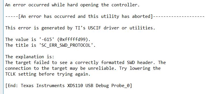
2. We went back to our original board (with a CC3200) and connected the CC2650 LP to it for debugging (as we have always done) and verified that it worked fine. But replacing the CC2650 LP with the CC3220 LP we get an SWD header error problem. We tried to reduce the frequency, but without any luck.

First of all I thought that using the external XDS110 out from any Launchpad would give the same result. Secondly, I am wondering why we are not able to connect to the CC3220 on our own modified board. The CC3220 on the Launchpad is a SF model while the one we have implemented on our own board is a S version. Could the flash content have any impact on the operation of the debugger?

Best regards,

Jan 

  • Hello,

    Just to understand clearly, you mentioned that you can connect to CC3220 on the LP and not on your custom board when using the XDS110. Which XDS, the one from CC2650 LP or CC3220LP? or maybe both?

    If the external XDS works fine on CC3220 LP but not on your custom board, please ensure that the logic lines for all SOP lines are stable and valid (not only the logic '1'). Maybe you have voltage levels that represents UARTLOAD mode and the device is stuck in boot loader mode.

    Regards,

    Shlomi

  • Hi!
    Sorry about the confusion. I can only connect to the CC3220 on the CC3220 LP (using the local XDS110 on the 3220 LP). When I try to connect to the CC3220 from another board (XDS110) it fails to get contact. Should I be able to use the XDS110 on the CC2650LP to debug the CC3220 on the CC3220 LP? I will check the SOP lines on the custom board. I see from the documentation that the value of one of the pull-down resistors could be changed...

    Best regards,
    Jan
  • Hi Jan,

    Yes, this should work without any issue. I have tested connection from CC3220 LaunchPad (XDS110) to CC3200 LaunchPad (XDS100) and vice versa without any issue.

    Do you have properly disconnected JTAG jumpers from internal MCU? Can you share photos of connection and jumpers configuration?

    Jan
  • Hi!

    We managed to get contact with the CC3220SF on the CC3220SF LP using the XDS110 debugger on the CC2650 LP. So that works after a little confusion about the jumpers. Now, we try to get connected to the CC3220S.which we have mounted on our own board. I changed the device from CC3220SF-SWD to CC3220S-SWD in the ccxml file, but I still get an error message when testing the connection I guess that should be sufficient to get in contact with the device?

    We have checked the levels on the SOP pins and they seems OK. I have read some post that the device could be stuck in some production mode not being able to access the JTAG pins. Could that be the case here?

    Best regards,

    Jan

  • Hi Jan,

    What exact error code do you see?

    Yes, this correct. In production mode is JTAG disconnected due to security reasons. To be able use JTAG/SWD you need to switch device into development mode by Uniflash software.

    Jan
  • Hi!

    Ok, lets assume the new 3220 is locked in production mode and the JTAG interface is disconnected. The only way to get the device into developer mode is then to use Uniflash to set switch the mode through the serial/UART lines? On our custom board we have a Silicon Labs CP210x USB to UART Bridge which we use to program the FLASH with Uniflash 3.4 when the CC3200 is present. Replacing the CC3200 with the CC3220 I assume we can use use the same USB connection with Uniflash V4. but setting the SOP to [010] ?

    The error I get when trying to connect via SWD is 

    Regards,

    Jan

  • Hi,

    Yes it should be possible do that. A few notes:

    • make sure that your chip is able use baudrate 921600
    • make sure that RX line or UART is held in high by your Silab converter in case of no data are transferred by UART. IN SOP mode [0 1 0] is berak signal during boot detected by low state of RX line at CC3220.
    • additional information you find here http://www.ti.com/lit/an/swra568/swra568.pdf

    My recommendation is to prepare image with devemopelmet mode in Uniflash GUI and that use Uniflash CLI to upload it. I am not sure if at new versions of Uniflash GUI is possible to select COM port. With some older versions of 4.x this was not possible and it was requred to use CLI version. Uniflash CLI code tested with version 4.2 (Uniflash project with name "test"):

    SET port=COM3
    SET upath=c:\ti\uniflash_4.0
    call %upath%\dslite.bat --mode cc3220 project program --name test --port %port% 

    In case of that you have CC3220 LaunchPad, you should check if error -615 is returned in case of device is in production mode. Without testing I am not able guarantee that this error is not returned in case of connection issue with SWD. Alternately you can search at e2e forum. I expect that you find more threads releated to error -615 with CC3220.

    BTW ... SOP mode [ 0 1 0 ] is for a JTAG (4-wires) not for a SWD. Just to be sure...

    Jan

  • Hi!

    Thanks for the reply. I have done what you have suggested, but from swra568.pdf I saw that I could use SOP [001] which also is the SOP mode for SWD which I have been using. Thus, from what I understand I do not need to take the RX signalling into account. As I do not have the MAC address of the device it is difficult for me to generate a gang image for development. I am also unable to connect with the CC3220 on my custom board with uniflash. However, I generated a production file version, just to see if I was able to download anything with the CLI command as you suggested. However, it failed with the error shown below.

    A couple of notes

    - the USB to UART bridge should support baud rates up to 1M.

    - I got the same error (-615) when programming the CC3220SF LP in production mode. But the same error I also get when SOP is set to [0 1 0] as this is for JTAG(4-wires) and not for SWD. So there can be more than one reason why I get this error.  

    - I see that the uniflash cannot connect to the CC3220 on the CC3220 LP if the SOP is set to [0 0 1]. Is this the reason why I need to use the CLI?

    Regards,

    Jan

  • Hi,

    To be able connect by Uniflash you need to use SOP mode [ 1 0 0 ] or [ 0 1 0 ] (2 1 0). Before entering to bootloader for flashing image is a device reset mandatory.

    Are you able execute your production image at CC3220 LaunchPad? Can you simulate connection with your LaunchPad with Silab chip? It may to be reasonable to simulate programming with LaunchPad and after you will be able do that continue to your hardware.

    Command above I use with Uniflash version 4.2. As I remember I had some issue with newer versions of Uniflash. But I don't know real reason, because I don't investigate that yet.

    BTW ... name parameters is a name of Uniflash project not a name of .sli file.

    BTW2 ... did you made all hardware changes recommended at http://www.ti.com/lit/zip/swru462

    Jan

  • Hi!

    Sorry about the mix up of the SOP lines, I ment [1 0 0] and not [0 0 1] in my previous post. In have also tried out the detect-devices script without getting any replies from the device on our custom board. We have also modified our board according to swru462. So I guess the next step will be to try to get the UART lines from the Silab chip on our custom board and feed them into the rx and tx lines on the CC3220 LP board, which is what I assume you mean by simulating the connection.

    Best regards,

    Jan

  • Hi,

    Testing of Slab chip and whole Uniflash work-flow with LP is a reasonable first step.

    Personally I think that there is also possibility that your hardware is not functioning after switching from CC3200 to CC3220. Do you use QFN or MOD package?

    Jan
  • Hi!

    We use a QFN package. I will also try to downgrade to Uniflash 4.2 as I have problems programming the CC3220SF LP with dslite. Will the fact that we are using CC3220S on our custom board have any effect on the programming compared to CC3220SF?

    Regards,

    Jan

  • Here is the latest log:

    OTA_init: sizeof CdnClient=576, sizeof OtaArchive=4404
    OTA_init: sizeof OtaLib_t=7184, sizeof OTA_memBlock=7800
    OTA_init: OTA lib version = OTA_LIB_2.0.0.7
    OtaArchive_Init: OTA archive version = OTA_ARCHIVE_2.0.0.4
    OtaConfig: call OTA_set EXTLIB_OTA_SET_OPT_SERVER_INFO, ServerName=api.dropbox.com
    OtaConfig: call OTA_set EXTLIB_OTA_SET_OPT_VENDOR_ID, VendorDir=OTA_MAGNETEK
    SignalOTAEvent
    3. Changing states: 6!!!
    Start of OTA update loop!
    Event: 10!!!
    StopAsyncEvtTimer
    OtaRunStep
    SignalOTAEvent
    Start of OTA update loop!
    Event: 10!!!
    StopAsyncEvtTimer
    OtaRunStep
    OTA_run: call CdnClient_ConnectServer OTA server=api.dropbox.com
    CdnClient_ConnectServer: HttpClient_Connect api.dropbox.com
    HttpClient_Connect: IP_ADDR=162.125.3.7
    SimpleLinkSockEventHandler
    SignalOTAEvent
    [SOCK ERROR] an event received on socket 0
    [SOCK ERROR] Used wrong CA to verify the peer.
    Please install the following Root Certificate:
    DigiCert High Assurance EV Root CA
    [SOCK EVENT] - Unexpected Event [20x]

    SignalOTAEvent
    HttpClient_Connect: ERROR Socket Connect, status=-688
    CdnClient_ConnectServer: ERROR HttpClient_Connect, Status=-20304
    OTA_run: ERROR CdnClient_ConnectServer, Status=-20304

    _OtaCheckConsecutiveErrors: ConsecutiveOtaErrors=1/5, return only WARNNING
    OtaRunStep: WARNING Ota_run, Status=20006, continue for next OTA retry

    SignalOTAEvent
    Start of OTA update loop!
  • Hi,

    I think not. These chips are pretty same at this.

    Jan
  • Hi again!

    After downloading Uniflash 4.2, I got some response using the CLI command that you gave me. It looks like the interface has changed somewhat in version 4.5. However, starting with the Launchpad, I am still not able to get the device up and running after programming the device with dslite running Uniflash4.2. I get the following error message

    INFO:root:The device type defined in the project settings differs from the type of the actual connected device
    Wrong device type, press ENTER to contine or CTRL-C to abort

    Trying to get the same file structure as I got to work in V4.5, it complains about a signature file name being empty when trying to program from Uniflash.

    So trying to program the Launchpad from 4.2 did not get me any further.

    Next I tried ImageProgramming in the Embedded Programming SDK. Here I tried to program a binary that I generated in V4.5. Everything seemed fine for a while, but in the end I got the following error 

    Step #11 --> Image programming
    Received error : error number = -10275 , extended error = 3904

    Although, I didn't get the image programming to complete, the responses were identical from the Launchpad and the custom board. The latter responded by being a CC3220S type, which is correct. This is the first response I got from the custom board, thus I have a hope that the problem is related to the fact that it is set in production mode. As I do not have the mac address to it, I need to do the following

    1. Solve the problem with UART programming

    2. Write a small program that will output the MAC address of the device. 

    3. Produce a production file and download the program over the UART

    4. When I get the MAC address of the device, I am able to make a development image and download that.

    5. In development mode I should be able to debug.

    Right now I just cant understand why I am not able to program the devices over the UART. Any suggestions would be appreciated.

    Best regards,

    Jan

  • Hi,

    Error -10275 could signalise that you not use proper format of file for embedded programming. Do you use .ucf file?

    Described procedure is possible, but it will necessary to properly do all steps to create image for device in production mode. That means you will need trusted certificate, etc.

    There could be two alternative ways:
    - Connect RX, TX, GND and Reset from LaunchPad to you board and try to use Uniflash GUI via UART in XDS110
    - There is a some "undocumented" way how to set exact COM port number for Uniflash GUI. As I remembered this was discussed at e2e forum few months ago. Unfortunately I am not able find that discussion thread now.

    Jan
  • Hi!

    You were right. I was using the bin file. When using the ucf file I managed to flash both the Launchpad and our custom board. No errors were reported anyway. However, when restarting the board only the Launchpad booted up as expected (presented itself through the CONSOLE). As our customboard didn't show the same behavior, we connected the RX,TX, GND and Reset from the LaunchPad to our board and got it connected. Here we verified that the CC3220 was set up in Production mode. Thus, by flashing our board we were avle to set it in Developer mode. However, our board did still not boot as expected. I thus, we tried to connect to it through the debugger again since it now was set in Developer mode. Setting SOP2-0[0 0 1], we now get the JTAG test to pass, but when trying to connect we get the following error messages: 

    Cortex_M4_0: Failed CPU Reset: (Error -2063 @ 0x0) Unable to reset device. Power-cycle the board. If error persists, confirm configuration and/or try more reliable JTAG settings (e.g. lower TCLK). (Emulation package 8.0.27.9)
    Cortex_M4_0: Trouble Halting Target CPU: (Error -2062 @ 0x0) Unable to halt device. Reset the device, and retry the operation. If error persists, confirm configuration, power-cycle the board, and/or try more reliable JTAG settings (e.g. lower TCLK). (Emulation package 8.0.27.9).

    Regards,

    Jan


  • Hi,

    I have done a quick investigation what can cause error  -2063. Unfortunately I was not able find more information. I suppose that error is caused by some hardware issue. I am not able say that can be reason of issue. It is hard to debug hardware issue if you even don't touch that particular hardware.

    - please check again that your hardware migration from CC3200 to CC3220 was done properly (Migration-QFN from swru462)
    - please try to use 4-wire JTAG (SOP [0 0 0]) instead for SWD for a test:

    • connect XDS-110 from LaunchPad (GND, TDO, TDI, TMS, TCK). Do not forgot disconnect jumpers fro a internal CC3220 at LaunchPad.
    • set SOP to [0 0 0] and restart your board
    • change target from SWD to JTAG in CCS
    • perform Test connection / JTAG Integrity test

    In case of that you was able upload image generated by Uniflash, it looks that your main clock works, power source (CC3220 DC-DC) is able works with small current at least, your UART connection is functional and connection with sFlash works as well.

    Maybe guys from TI App team could have any idea especially with error -2063 during connecting to target.

    Jan

  • Hi!

    Thanks for reply. We only support 2-wire JTAG on our board and would need further modifications to do 4-wire. We have gone through the migration report and modified our board accordingly. So everything should be up to data regarding the HW. The strange thing is that the integrity passes but the error turns up when running the debugger. Have you found out anything more about the error message -2063?

    Regards,

    Jan

  • Hi,

    As to be honest, I am not surprised that you passed JTAG integrity test, but JTAG connection is not functional. Integrity test can return success even connection is not proper. I am not sure about SWD, but one example with 4-wire JTAG. Use 4-wire JTAG, and connect TDI and TDO together. Result of integrity test will be success.

    Sorry, no. I haven't additional information about error -2063? You should ask question at CCS forum.

    Jan

  • Hi!

    We are not getting any closer solving this issue. We have gone through the migration list and done some more trials without any success. The only thing we are a bit uncertain about is the size of the FLASH. In the migration document it states that it should be replaced by a 32MBit FLASH. We have 16MBit FLASH on our custom board and have not changed this as it should be large enough according to the spec. Do you agree with that, or is this crucial in order for the CC3220 to have correct operation. Shouldn't the Uniflash complain when programming it, if it wasn't large enough?

    We have also tried to lower the clock frequency and checked the logic levels of the reset and jtag lines. As we can't detect any signalling on the reset lines, I assume that the CPU reset to halt the target is done by signalling a certain reset word over the jtag lines and not over the reset line. Based on the error message from the debugger I assume that this is the result of the problem we are experiencing. If so, the cause of the problem is either bad signal quality on the jtag lines or the CC3220 running in a undefined state. The first could be solved by lowering the frequency, but the latter I have no idea of how to find out of. Do you have any further suggestions of what to investigate except from trying 4-wire jtag? 

    Regards,

    Jan

  • Hi,

    Even though you don't have Flash with recommended size, I think this is not a issue in your case. This recommendation comes from size of XIP flash (1MB) and ability to store whole 1MB image into sFlash.

    I don't think that usage of 4-wire JTAG will "magically" fix your issue somehow. Usage ot 4-wire JTAG was one of another suggestions what you should try. I haven't other ideas. Please wait for answer at CSS forum about interpretation of error code.

    Jan
  • Hi Jan,

    I'm going to close this thread since we determined on your other thread that we'll do a schematic review: e2e.ti.com/.../754737

    Best regards,
    Sarah