This thread has been locked.

If you have a related question, please click the "Ask a related question" button in the top right corner. The newly created question will be automatically linked to this question.

CCS/TMDSEMU110-U: Programming/Debugging Error

Part Number: TMDSEMU110-U
Other Parts Discussed in Thread: CC3220SF

Tool/software: Code Composer Studio

Hi,

I couldn't Verify "TMDSEMU110-U" device on Code Composer Studio. I use 9.0.1.00004 Version. And ı get below message when I verify device. could you please help me at this issue? How I can fix this problem?

[Start]

Execute the command:

%ccs_base%/common/uscif/dbgjtag -f %boarddatafile% -rv -o -S integrity

[Result]


-----[Print the board config pathname(s)]------------------------------------

C:\Users\Kemal-PC\AppData\Local\Texas Instruments\
    CCS\ccs901\1\0\BrdDat\testBoard.dat

-----[Print the reset-command software log-file]-----------------------------

This utility has selected a 100- or 510-class product.
This utility will load the adapter 'jioxds110.dll'.
The library build date was 'Mar 25 2019'.
The library build time was '17:36:26'.
The library package version is '8.1.0.00007'.
The library component version is '35.35.0.0'.
The controller does not use a programmable FPGA.

An error occurred while hard opening the controller.

-----[An error has occurred and this utility has aborted]--------------------

This error is generated by TI's USCIF driver or utilities.

The value is '-267' (0xfffffef5).
The title is 'SC_ERR_XDS110_TARGET_SUPPLY'.

The explanation is:
The controller could not detect valid target supply. Check target
JTAG connection and/or connection setting specifying voltage level.

[End]
  • Hello,

    Please double-check your target board is getting proper power. Check the TVRef pin. It is often caused by bad connectors.

    There are many threads on the forum for this issue:

    https://e2e.ti.com/support/tools/ccs/f/81/t/936847

    https://e2e.ti.com/support/tools/ccs/f/81/t/726524

    Thanks

    ki

  • Hi,

    My problem is a bit different from these issues.I don't connect JTAG cable to my board. I only connect "TMDSEMU110-U" device to PC and press verify button at CCS IDE side. And ı get this error message. Firstly, How should I verify device from CCS IDE side?

    Thanks.

  • Hi,

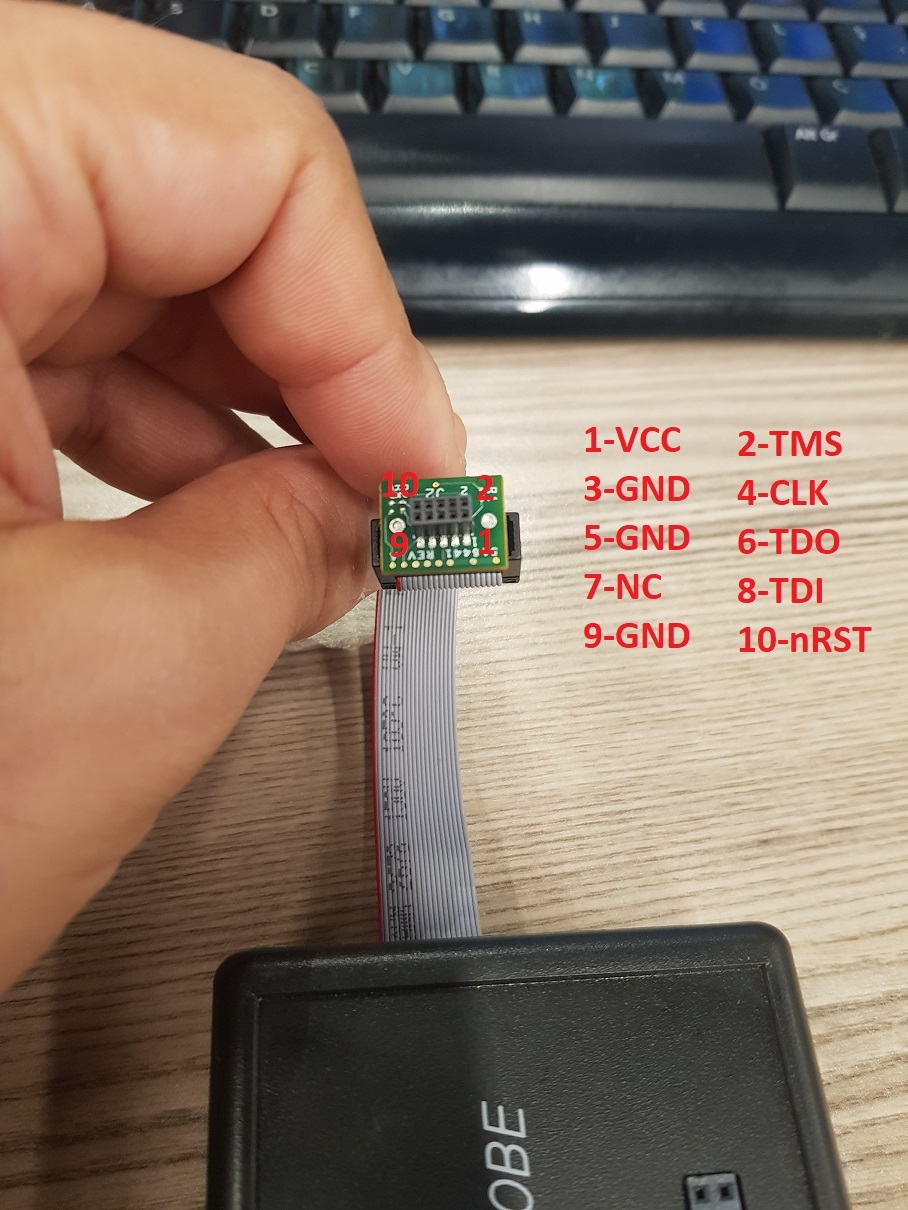
    Could you please check the marked pinout of XDS110 are True or Not? I marked Pin numbers and definitions at below picture. I couldn't verify device with my board. My Board's JTAG Connector pinout (schematic and PCB) are defined at below also. Could you please check the pinouts and inform me? I want to only be sure my connections are True when I plugged XDS110's ARM 10 Cable to my board?

  • Hİ,

    I proceeded at circuit side and I could successfully verified the my circuit over TSDSEMU110U Programming device; But unfortunately I have not programmed device, yet. I got below messages. So could you check device pinout which I asked at my last post at top and confirm pins' connections are True? 

    [Start]

    Execute the command:

    %ccs_base%/common/uscif/dbgjtag -f %boarddatafile% -rv -o -S integrity

    [Result]


    -----[Print the board config pathname(s)]------------------------------------

    C:\Users\Kemal-PC\AppData\Local\Texas Instruments\
    CCS\ccs901\1\0\BrdDat\testBoard.dat

    -----[Print the reset-command software log-file]-----------------------------

    This utility has selected a 100- or 510-class product.
    This utility will load the adapter 'jioxds110.dll'.
    The library build date was 'Mar 25 2019'.
    The library build time was '17:36:26'.
    The library package version is '8.1.0.00007'.
    The library component version is '35.35.0.0'.
    The controller does not use a programmable FPGA.
    The controller has a version number of '5' (0x00000005).
    The controller has an insertion length of '0' (0x00000000).
    This utility will attempt to reset the controller.
    This utility has successfully reset the controller.

    -----[Print the reset-command hardware log-file]-----------------------------

    The scan-path will be reset by toggling the JTAG TRST signal.
    The controller is the XDS110 with USB interface.
    The link from controller to target is direct (without cable).
    The software is configured for XDS110 features.
    The controller cannot monitor the value on the EMU[0] pin.
    The controller cannot monitor the value on the EMU[1] pin.
    The controller cannot control the timing on output pins.
    The controller cannot control the timing on input pins.
    The scan-path link-delay has been set to exactly '0' (0x0000).

    -----[Perform the Integrity scan-test on the JTAG IR]------------------------

    This test will use blocks of 64 32-bit words.
    This test will be applied just once.

    Do a test using 0xFFFFFFFF.
    Scan tests: 1, skipped: 0, failed: 0
    Do a test using 0x00000000.
    Scan tests: 2, skipped: 0, failed: 0
    Do a test using 0xFE03E0E2.
    Scan tests: 3, skipped: 0, failed: 0
    Do a test using 0x01FC1F1D.
    Scan tests: 4, skipped: 0, failed: 0
    Do a test using 0x5533CCAA.
    Scan tests: 5, skipped: 0, failed: 0
    Do a test using 0xAACC3355.
    Scan tests: 6, skipped: 0, failed: 0
    All of the values were scanned correctly.

    The JTAG IR Integrity scan-test has succeeded.

    -----[Perform the Integrity scan-test on the JTAG DR]------------------------

    This test will use blocks of 64 32-bit words.
    This test will be applied just once.

    Do a test using 0xFFFFFFFF.
    Scan tests: 1, skipped: 0, failed: 0
    Do a test using 0x00000000.
    Scan tests: 2, skipped: 0, failed: 0
    Do a test using 0xFE03E0E2.
    Scan tests: 3, skipped: 0, failed: 0
    Do a test using 0x01FC1F1D.
    Scan tests: 4, skipped: 0, failed: 0
    Do a test using 0x5533CCAA.
    Scan tests: 5, skipped: 0, failed: 0
    Do a test using 0xAACC3355.
    Scan tests: 6, skipped: 0, failed: 0
    All of the values were scanned correctly.

    The JTAG DR Integrity scan-test has succeeded.

    [End]

  • What device and board are you using? Is it a custom board?

  • Hi,

    Yes it is custom board which we designed with CC3220SF Core. I defined its programming connector at top side. My CC3220SF connection schematic is same with CC3220SF LaunchPad reference schematic.

    Could you help me about this issue ASAP please. If you have any question or document I can provide. I am waiting your suggestions.

    Thanks.

  • I will move this thread to the device forum for further assistance.

  • Hi,

    Will I get any response today? And will I follow issue from this topic?

    Thanks.

  • Hi,

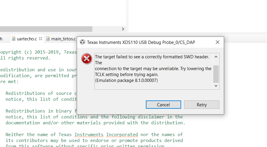
    The error message provided in CCS indicates that you are using SWD mode for the debugger connection.

    What settings do you have for the SOP pins (p21, p34-35)? In order for the device to allow for SWD connections, you will need to have SOP[2:0] be set to 001.

    See table 6.6 of the datasheet for a description of the various SOP modes:

    https://www.ti.com/lit/ds/symlink/cc3220s.pdf

    Also, have you programmed your CC3220SF so that it is in development mode? As part of the bring up process, you will need to program the CC3220SF serial flash, and you will need to set the device into development mode in order to unlock debug access. Some instructions can be found here: https://www.ti.com/lit/swru469

    Regards,

    Michael