This thread has been locked.

If you have a related question, please click the "Ask a related question" button in the top right corner. The newly created question will be automatically linked to this question.

CC2652RSIP: Emulate CC2520 using CC2652 & run SimpliciTI stack

Part Number: CC2652RSIP
Other Parts Discussed in Thread: CC2520, SYSCONFIG

Hi,

I am exploring posibilities to emulate CC2520 by using CC2652RSIP.

That means CC2652 receives commands, parse them very quickly and gets ready to reply in next SPI transmition.

Commands are specified on page 52 of datasheet cc2520.pdf

Has anyone tried something similar?

Thank you in advanced!

Best regards,

Ivan Sojic

  • Hi Ivan,

    If you want to replicate 2.4 GHz Proprietary RF transceiver functionality then I recommend you evaluate the rfEasyLinkNp example.  You can review the README, EasyLink Network Processor SimpleLink Academy Lab, and Proprietary RF User's Guide to get started.  However, please note that only UART communication is supported by default and  AT commands differ from the requested CC2520 instruction sets, thus some migration will be required and full emulation should not be expected.

    Regards,
    Ryan

  • Hi Ryan,

    Thanks for the reply. 

    I have checked the rfEasyLinkNp example and documentation that you pointed out. Example runs on my eval board. Unfortunatelly using UART is currently not possible at the end hardware. So I continued with an examples using SPI. For that I have selected spislave example.

    Here I have one question. I cannot configure a board (spi slave) to send a multiple bytes for a single CS assertion from spi master (eg. receive 3 Bytes when CS is low).

    Following config I have tried:  

    Using hardware CS

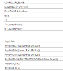
    In SysConfig: MX25R8035F SPI Flash & Four Pin SS Active Low. 

    In case SPI master is sending 3 Bytes, when SPI slave is spiParams.dataSize = 8;, spi slave will clock out only 1 byte for each CS assertion. For clk from other 2 Bytes, MISO is zero.

    In case dataSize is 16, spiSlave (my device) will clock out 2 Bytes for each CS assertion. For 3rd Byte MISO is again zero.

    For this scenario, if I de-assert and assert CS on the spi master after each byte, spi slave will send 3x 1Byte and report that all data are sent.

    In the attached documentation from SPI.h doxygen, I found a part about "asserting CS over several SPI data frames". What I don't understand completely what should be done on SPI slave in this case.

    Software CS shall be used (Three pin config in SysConfig). Shall spi slave de-assert and assert a CS pin after every frame?

    Could you please help me here? 

    Thanks and best regards,

    Ivan

    ------------------------------------

    "Asserting on Chip Select

    The SPI protocol requires that the SPI master asserts a SPI slave's chip select pin prior to starting a SPI transaction. While this protocol is generally followed, various types of SPI peripherals have different timing requirements as to when and for how long the chip select pin must remain asserted for a SPI transaction.

    Commonly, the SPI master uses a hardware chip select to assert and de-assert the SPI slave for every data frame. In other cases, a SPI slave imposes the requirement of asserting the chip select over several SPI data frames. This is generally accomplished by using a regular, general-purpose output pin. Due to the complexity of such SPI peripheral implementations, this SPI driver has been designed to operate transparently to the SPI chip select. When the hardware chip select is used, the peripheral automatically selects/enables the peripheral. When using a software chip select, the application needs to handle the proper chip select and pin configuration. Chip select support will vary per SPI peripheral, refer to the device specific implementation documentation for details on chip select support.

    • Hardware chip select No additional action by the application is required.
    • Software chip select The application needs to handle the chip select assertion and de-assertion for the proper SPI peripheral."

  • Hey Ivan,

    The expected behavior is that the SPI slave will transfer as many bytes from its buffer as is possible so long as the CS pin is asserted and the SPI master continues to driver the SPI clock line.  Does the SPI slave confirm that three bytes are received while only sending out one?  Can a logic analyzer or oscilloscope screenshot be provided alongside a terminal display of the ongoing communication to further show the issue at hand?  Please note that the spislave example is intended to be used alongside the spimaster example so it would be best to evaluate these examples as intended before comparing behavior against a different master SPI MCU.  There are optional pins like CONFIG_SPI_MASTER_READY/CONFIG_SPI_SLAVE_READY which can be removed if not necessary.

    Where it pertains to chip select, a four-pin mode with hardware chip select is preferred so long as the SPI master MCU is capable of properly driving the pin.  This would require no further action for the application.  With three-pin mode, or software chip select, the SPI slave application must determine whether to transfer slave data or enable/disable the peripheral regardless of the interactions taking place on the SPI pins from the master.  This is more feasible if the SPI slave is the only device being controlled by the master on the same SPI lines (for instance, the MS25R8035F is shut off in the example through Boart_init -> Board_shutDownExtFlash.

    Regards,
    Ryan

  • Hi Ryan,

    Please find enclosed a sample project. CONFIG_SPI_MASTER_READY/CONFIG_SPI_SLAVE_READY are not used in my example.

    Description of the signals: ch1 - CS, ch2 - MISO, ch3 - MOSI, ch4 - CLK

    SPI slave shall send 3 first Bytes from "Hello from slave".

    SPI master are sending 0x10 0x40 0x80 (as in the image bellow).

    SPI slave answers every time with only one Byte. If above command is repeated on SPI master side (with CS deasserting and asserting), SPI slave will send "e" and 3rd time "l". After 3rd time, SPI slave will report that 3 Bytes are sent and callback is called.

     spislave_LP_CC2652RSIP_tirtos7_ccs.zip

    Terminal is printing following.

    1. Terminal will record
    2. Starting the SPI slave example
    3. This example requires external wires to be connected to the header pins. Please see the Board.html for details.
    4. Slave SPI initialized
    5. Slave received: 0x10 0x10 0x10
    Does the SPI slave confirm that three bytes are received while only sending out one?

    It is also interested that SPI slave has only recieved a first byte (0x10) each time! After repeating a command 3x on SPI master side, SPI slave will confirm that 3 Bytes are received.

    With three-pin mode, or software chip select, the SPI slave application must determine whether to transfer slave data or enable/disable the peripheral regardless of the interactions taking place on the SPI pins from the master.  This is more feasible if the SPI slave is the only device being controlled by the master on the same SPI lines

    This is a case for my application. I would not necessarily need a CS. When I tried to configure SPI in a Three Pin mode, no data were sent. How I can enable SPI slave from the source code?

    Thanks, Ivan

  • Thanks for the additional information.  I was able to create a similar setup and produce problematic behavior as well.  These were greatly reduced after following the recommendations from this previous thread: https://e2e.ti.com/f/1/t/1078279 

    /*
     *  ======== spislave.c ========
     */
    #include <stddef.h>
    #include <stdbool.h>
    #include <stdint.h>
    #include <string.h>
    
    /* POSIX Header files */
    #include <pthread.h>
    #include <semaphore.h>
    #include <unistd.h>
    
    /* Driver Header files */
    #include <ti/drivers/GPIO.h>
    #include <ti/drivers/SPI.h>
    #include <ti/display/Display.h>
    
    #include <ti/devices/cc13x2_cc26x2/driverlib/ssi.h>
    #include <ti/drivers/spi/SPICC26X2DMA.h>
    
    /* Driver configuration */
    #include "ti_drivers_config.h"
    
    #define THREADSTACKSIZE (1024)
    
    #define SPI_MSG_LENGTH  (4)
    #define SLAVE_MSG       ("Sl")
    
    #define MAX_LOOP        (10)
    
    static Display_Handle display;
    
    unsigned char slaveRxBuffer[SPI_MSG_LENGTH];
    unsigned char slaveTxBuffer[SPI_MSG_LENGTH];
    
    /* Semaphore to block slave until transfer is complete */
    sem_t slaveSem;
    
    /* Status indicating whether or not SPI transfer succeeded. */
    bool transferStatus;
    
    static void flushFifos(SPICC26X2DMA_HWAttrs const *hwAttrs);
    
    /*
     *  ======== transferCompleteFxn ========
     *  Callback function for SPI_transfer().
     */
    void transferCompleteFxn(SPI_Handle handle, SPI_Transaction *transaction)
    {
        if (transaction->status != SPI_TRANSFER_COMPLETED) {
            transferStatus = false;
        }
        else {
            transferStatus = true;
        }
    
        sem_post(&slaveSem);
    }
    
    /*
     * ======== slaveThread ========
     *  Slave SPI sends a message to master while simultaneously receiving a
     *  message from the master.
     */
    void *slaveThread(void *arg0)
    {
        SPI_Handle      slaveSpi;
        SPI_Params      spiParams;
        SPI_Transaction transaction;
        uint32_t        i;
        bool            transferOK;
        int32_t         status;
    
        /*
         * CONFIG_SPI_MASTER_READY & CONFIG_SPI_SLAVE_READY are GPIO pins connected
         * between the master & slave.  These pins are used to synchronize
         * the master & slave applications via a small 'handshake'.  The pins
         * are later used to synchronize transfers & ensure the master will not
         * start a transfer until the slave is ready.  These pins behave
         * differently between spimaster & spislave examples:
         *
         * spislave example:
         *     * CONFIG_SPI_MASTER_READY is configured as an input pin.  During the
         *       'handshake' this pin is read & a high value will indicate the
         *       master is ready to run the application.  Afterwards, the pin is
         *       read to determine if the master has already opened its SPI pins.
         *       The master will pull this pin low when it has opened its SPI.
         *
         *     * CONFIG_SPI_SLAVE_READY is configured as an output pin.  During the
         *       'handshake' this pin is changed from low to high output.  This
         *       notifies the master the slave is ready to run the application.
         *       Afterwards, the pin is used by the slave to notify the master it
         *       is ready for a transfer.  When ready for a transfer, this pin will
         *       be pulled low.
         *
         * Below we set CONFIG_SPI_MASTER_READY & CONFIG_SPI_SLAVE_READY initial
         * conditions for the 'handshake'.
         */
    //    GPIO_setConfig(CONFIG_SPI_SLAVE_READY, GPIO_CFG_OUTPUT | GPIO_CFG_OUT_LOW);
    //    GPIO_setConfig(CONFIG_SPI_MASTER_READY, GPIO_CFG_INPUT);
    
        /*
         * Handshake - Set CONFIG_SPI_SLAVE_READY high to indicate slave is ready
         * to run.  Wait for CONFIG_SPI_MASTER_READY to be high.
         */
    //    GPIO_write(CONFIG_SPI_SLAVE_READY, 1);
    //    while (GPIO_read(CONFIG_SPI_MASTER_READY) == 0) {}
    
        /*
         * Create synchronization semaphore; this semaphore will block the slave
         * until a transfer is complete.  The slave is configured in callback mode
         * to allow us to configure the SPI transfer & then notify the master the
         * slave is ready.  However, we must still wait for the current transfer
         * to be complete before setting up the next.  Thus, we wait on slaveSem;
         * once the transfer is complete the callback function will unblock the
         * slave.
         */
        status = sem_init(&slaveSem, 0, 0);
        if (status != 0) {
            Display_printf(display, 0, 0, "Error creating slaveSem\n");
    
            while(1);
        }
    
        /*
         * Wait until master SPI is open.  When the master is configuring SPI pins
         * the clock may toggle from low to high (or high to low depending on
         * polarity).  If using 3-pin SPI & the slave has been opened before the
         * master, clock transitions may cause the slave to shift bits out assuming
         * it is an actual transfer.  We can prevent this behavior by opening the
         * master first & then opening the slave.
         */
    //    while (GPIO_read(CONFIG_SPI_MASTER_READY)) {}
    
        /*
         * Open SPI as slave in callback mode; callback mode is used to allow us to
         * configure the transfer & then set CONFIG_SPI_SLAVE_READY high.
         */
        SPI_Params_init(&spiParams);
        spiParams.frameFormat = SPI_POL0_PHA0;
        spiParams.mode = SPI_SLAVE;
        spiParams.transferCallbackFxn = transferCompleteFxn;
        spiParams.transferMode = SPI_MODE_CALLBACK;
        slaveSpi = SPI_open(CONFIG_SPI_SLAVE, &spiParams);
        if (slaveSpi == NULL) {
            Display_printf(display, 0, 0, "Error initializing slave SPI\n");
            while (1);
        }
        else {
            Display_printf(display, 0, 0, "Slave SPI initialized\n");
        }
    
        /* Copy message to transmit buffer */
        strncpy((char *) slaveTxBuffer, SLAVE_MSG, SPI_MSG_LENGTH);
    
        for (i = 0; i < MAX_LOOP; i++) {
            /* Initialize slave SPI transaction structure */
            slaveTxBuffer[sizeof(SLAVE_MSG) - 1] = (i % 10) + '0';
            memset((void *) slaveRxBuffer, 0, SPI_MSG_LENGTH);
            transaction.count = SPI_MSG_LENGTH;
            transaction.txBuf = (void *) slaveTxBuffer+1;
            transaction.rxBuf = (void *) slaveRxBuffer;
    
            /* Toggle on user LED, indicating a SPI transfer is in progress */
            GPIO_toggle(CONFIG_GPIO_LED_1);
    
            /*
             * Setup SPI transfer; CONFIG_SPI_SLAVE_READY will be set to notify
             * master the slave is ready.
             */
            flushFifos(slaveSpi->hwAttrs);
            SSIDataPut(SSI0_BASE, (uint32_t) slaveTxBuffer[0]);
            transferOK = SPI_transfer(slaveSpi, &transaction);
            if (transferOK) {
    //            GPIO_write(CONFIG_SPI_SLAVE_READY, 0);
    
                /* Wait until transfer has completed */
                sem_wait(&slaveSem);
    
                /*
                 * Drive CONFIG_SPI_SLAVE_READY high to indicate slave is not ready
                 * for another transfer yet.
                 */
    //            GPIO_write(CONFIG_SPI_SLAVE_READY, 1);
    
                if (transferStatus == false) {
                    Display_printf(display, 0, 0, "SPI transfer failed!");
                }
                else {
                    Display_printf(display, 0, 0, "Slave received: %s",
                            slaveRxBuffer);
                }
            }
            else {
                Display_printf(display, 0, 0, "Unsuccessful slave SPI transfer");
            }
        }
    
        SPI_close(slaveSpi);
    
        /* Example complete - set pins to a known state */
    //    GPIO_setConfig(CONFIG_SPI_MASTER_READY, GPIO_CFG_OUTPUT | GPIO_CFG_OUT_LOW);
    //    GPIO_write(CONFIG_SPI_SLAVE_READY, 0);
    
        Display_printf(display, 0, 0, "\nDone");
    
        return (NULL);
    }
    
    /*
     *  ======== mainThread ========
     */
    void *mainThread(void *arg0)
    {
        pthread_t           thread0;
        pthread_attr_t      attrs;
        struct sched_param  priParam;
        int                 retc;
        int                 detachState;
    
        /* Call driver init functions. */
        Display_init();
        GPIO_init();
        SPI_init();
    
        /* Configure the LED pins */
        GPIO_setConfig(CONFIG_GPIO_LED_0, GPIO_CFG_OUT_STD | GPIO_CFG_OUT_LOW);
        GPIO_setConfig(CONFIG_GPIO_LED_1, GPIO_CFG_OUT_STD | GPIO_CFG_OUT_LOW);
    
        /* Open the display for output */
        display = Display_open(Display_Type_UART, NULL);
        if (display == NULL) {
            /* Failed to open display driver */
            while (1);
        }
    
        /* Turn on user LED */
        GPIO_write(CONFIG_GPIO_LED_0, CONFIG_GPIO_LED_ON);
    
        Display_printf(display, 0, 0, "Starting the SPI slave example");
        Display_printf(display, 0, 0, "This example requires external wires to be "
            "connected to the header pins. Please see the Board.html for details.\n");
    
        /* Create application thread */
        pthread_attr_init(&attrs);
    
        detachState = PTHREAD_CREATE_DETACHED;
        /* Set priority and stack size attributes */
        retc = pthread_attr_setdetachstate(&attrs, detachState);
        if (retc != 0) {
            /* pthread_attr_setdetachstate() failed */
            while (1);
        }
    
        retc |= pthread_attr_setstacksize(&attrs, THREADSTACKSIZE);
        if (retc != 0) {
            /* pthread_attr_setstacksize() failed */
            while (1);
        }
    
        /* Create slave thread */
        priParam.sched_priority = 1;
        pthread_attr_setschedparam(&attrs, &priParam);
    
        retc = pthread_create(&thread0, &attrs, slaveThread, NULL);
        if (retc != 0) {
            /* pthread_create() failed */
            while (1);
        }
    
        return (NULL);
    }
    
    static void flushFifos(SPICC26X2DMA_HWAttrs const *hwAttrs)
    {
        /* Flush RX FIFO */
        while(HWREG(hwAttrs->baseAddr + SSI_O_SR) & SSI_RX_NOT_EMPTY) {
            /* Read element from RX FIFO and discard */
            HWREG(hwAttrs->baseAddr + SSI_O_DR);
        }
    
        /* Enable TESTFIFO mode */
        HWREG(hwAttrs->baseAddr + 0x00000080) = 0x2;
    
        /* Flush TX FIFO */
        while(!(HWREG(hwAttrs->baseAddr + SSI_O_SR) & SSI_TX_EMPTY)) {
            /* Read element from TX FIFO and discard */
            HWREG(hwAttrs->baseAddr + 0x0000008C);
        }
    
        /* Disable TESTFIFO mode */
        HWREG(hwAttrs->baseAddr + 0x00000080) = 0x0;
    }

    Please let me know if this improves your setup as well.

    Regards,
    Ryan

  • Hi Ryan,

    Sorry for the late reply. 

    Did you use hardware CS in your example above? On my setup I still have to deassert and assert the CS after every frame.

    When using 4 Pin SS, I have a possibility to choose only DIO20 (Flash_CS). How I can select DIO11 (SPI_CS)? What is SPI_CS meant for?

    Thanks, Ivan

  • Hi Ryan,

    Do you have any update on my question above?

    Thanks, Ivan

  • I believe 4-pin hardware cs mode was evaluated to best replicate your setup.  You can switch the PinMux selection of SPI pins by changing the "Use Hardware" option from "MX25R8035F SPI Flash" to "None".  SPI_CS is the SPI SS Pin to determine when the device (de)asserts.

    Regards,
    Ryan

  • Hi Ryan,

    Thanks for the hint. I did a SPI configuration w/o "Use Hardware" and there I was able to select another CS (SPI_CS). 

    There is one more clarification before I close this issue:

    According to "CC13x2_CC26x2 SimpleLink Wireless MCU - TechnicalReferenceManual.pdf" on page 1796 - Motorola SPI Frame Format With SPO = 0 and SPH = 0,  where it says:

    "For continuous back-to-back transmissions, the SSIn_FSS signal must pulse high between each data word transfer because the slave-select pin freezes the data in its serial peripheral register and does not allow altering of the data if the SPH bit is clear. The master device must raise the SSIn_FSS pin of the slave device between each data transfer to enable the serial peripheral data write.  When the continuous transfer completes, the SSIn_FSS pin is returned to its  IDLE state one SSIn_CLK period after the last bit is captured"

    Based on that, I would assume that SPI slave is not possible with Three pin mode. Ans CS hat to pusle after every frame. Is that correct?

    Thanks, Ivan

  • Chip select is optional but highly recommended.  The SPI slave can still process communication using other parameters but the configuration is made more difficult.

    Regards,
    Ryan