This thread has been locked.

If you have a related question, please click the "Ask a related question" button in the top right corner. The newly created question will be automatically linked to this question.

CC2652P: No acces to high RF power (20 dBm)

Part Number: CC2652P
Other Parts Discussed in Thread: Z-STACK, CC1352P, CC2652R, SYSCONFIG

Hi, I am the very end user. I baught a Zigbee USB gateway with a CC2652P chip to have the high RF power of +20 dBm for longer distances. I flashed the newest Z-Stack coordinator firmware 'CC1352P2_CC2652P_launchpad_coordinator_20220219', and expected to have the high RF power available. But the USB stick fires disappointingly with very low power, presumably ~ 5 dBm (or lower?) - this indepently on the firmware powwer settings.

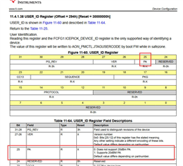
So I have searched for reasons in the available literature, and I found the following facts in the TI document SWCU185E (CC13x2, CC26x2 Technical Reference Manual):
In table 11-64 "USER_ID Register Field Descriptions" Bit 25 is explained:
> PA = 0: 'Does not support 20 dBm PA)
> PA = 1: 'Supports 20 dBm PA)
> Default value differs depending on partnumber.

Do I understand this correctly?
If this PA Bit is set to zero, no firmware in the world can't turn on high RF power???

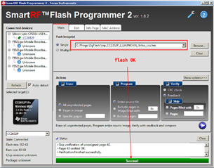
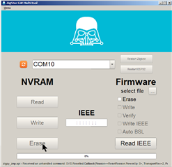
I used the TI SmartRF Flash Programmer 2 to read oud the USER_ID information at address 0x294, and found '00'; that means all 8 bits equal zero -> PA bit = 0. If my previously asked question is to be answered with "yes", then this would probably be the explanation.

I tried to set the first byte to '02' (PA bit = 1) and to write back the data block, but the flash program acknowledged this action with an error message:
 "Erasing info page not supported via serial bootloader".
 How can I set this PA bit to 1?

CC2652P - PA-Bit in FCFG Registers.pdf

  • Is your CC2652P hardware design complete the same as CC1352P launchpad? If not, I don’t think you can directly use CC1352P2_CC2652P_launchpad_coordinator_20220219 which looks like dedicated for launchpad.

  • > Is your CC2652P hardware design complete the same as CC1352P launchpad?

    I am pretty sure, it is.

    It's a matter of a SONOFF Zigbee 3.0 USB Dongle; stick comes pre-flashed with a Z-Stack 3.x.0 coordinator firmware. The manufacturer itself recommends the firmware from 'github.com/.../Z-Stack-firmware', from where I've got that mentioned firmware.

    My real question was:

    What about the PA Bit?

  • TX power is configured in firmware and you have to rebuild firmware if you want to change it. By the way, how do you measure that your USB stick fires disappointingly with very low power, presumably ~ 5 dBm (or lower?)

  • > TX power is configured in firmware and you have to rebuild firmware if you want to change it

    The firmware 'CC1352P2_CC2652P_launchpad_coordinator_20220219' can be configured through Zigbee2MQTT with parameter 'transmit_power: 20' in the configuration.yaml file.

    > By the way, how do you measure that your USB stick fires disappointingly with very low power, presumably ~ 5 dBm (or lower?)

    I have used two independent measuring methods:

    1)

    I have six movable Tuya Zigbee PIR sensors, which report the reiceived signal strength (called linkquality). I compared these results with those results, which I achieved with my Conbee II stick. From this stick I know, that it fires with +10 dBm (manufaturer statement). And the signals for the Sonoff stick were very much lower (by a factor of 3 ... 5) than with the Conbee stick. This was independent on the setting 'transmit_power: xx', I mentioned above.

    2)

    I measured the current which the Zigbee stick drains of from the USB supply. TI states for the CC2652P that the supply current will increase from 9.6 mA for 5 dBm up to 85 mA for +20 dBm. This large difference can be measured easily by current measurement!

    Here are my test results:

    1. Sonoff Zigbee 3.0 USB dongle with setting 'transmit_power: 5': Current from USB supply = 26.6 mA
    2. Sonoff Zigbee 3.0 USB dongle with setting 'transmit_power: 20': Current from USB supply = 26.5 mA

    The results are the same and independent of the transmit_power setting.

  • I am not familiar with Zigbee2Mqtt project. I suppose it uses MT command to set ZNP tx power and I would suggest you to use ZTool with SYS_SET_TX_POWER command to set tx power to verify if set TX power command works normally on firmware CC1352P2_CC2652P_launchpad_coordinator_20220219 first.

  • > I would suggest you to use ZTool with SYS_SET_TX_POWER command to set tx power to verify if set TX power command works normally

    I don't know anything about Z-Tool. But I will give it a try - Is it part of the Z-Stack 3.0.2 software pack?

    For the record:

    What about the PA Bit setting in Byte 0x294?

  • Yes, ZTool is part of the Z-Stack 3.0.2 software pack. I don’t understand what you mean “What about the PA Bit setting in Byte 0x294?”

  • > I don’t understand what you mean

    Read my top entry!

    For clarification: screenshot of TI document

  • I don't think you can directly manipulate this to make it work. I see CC1352P2_CC2652P_launchpad_coordinator_20211217 is reported as tested firmware here. Maybe you can download to have a try. Do you have any suggestion on this?

  • We already verified that the MT TX power command is called correctly. Question: is the PA bit set in the firmware or is it something read only in the chip?

  • I suppose this is configured by sysconf. When you set TX power equal or above 14 dbm, it will enable PA. If TX power is set less than 14 dbm, PA is disable. The problem is I am not sure what TX power is set when building  CC1352P2_CC2652P_launchpad_coordinator_20211217 and CC1352P2_CC2652P_launchpad_coordinator_20220219.

  • I build ZNP with 20dbm TX pwer for CC1352P-2 LaunchPad and attached the firmware for your reference. Maybe you can try it on your SONOFF Zigbee 3.0 USB Dongle and see if it works.

    4774.znp_CC1352P_2_LAUNCHXL_tirtos_ccs.zip

  • ...

    > Maybe you can try it on your SONOFF Zigbee 3.0 USB Dongle and see if it works.

    Unfortunately no.

    I use alwasy the same procedure:

    1) Flash with SmartRF Flasher

    2) Erase NVRAM with ZigStar Multitool

    3) Test with Zigbee2MQTT

    Here screen shots for the results:

    1st: With CC1352P2_CC2652P_launchpad_coordinator_20220219

    2nd: With your test firmware:

    See status line of ZigStar Multitool when starting 'Erase'

    Afterwards

    Failure of Zigbee2MQTT

    Summary:

    This test firmware doesn't work with the Sonoff stick.

    That's the same result as for other ZNP firmwares I tested before:

    e.g. znp_CC1352P_E72_20220301

  • Hi,

    Have you tried SmartRF Studio to test your board? You can set the TX power there, and run fundamental RF tasks such as continuous TX.
    https://www.ti.com/tool/SMARTRFTM-STUDIO

    This will ensure that the HW design is at least working.

    Thanks,
    Toby

  • ,,,
    > Have you tried SmartRF Studio to test your board?
    I have tried it now; unfortunately without succes: See page #1 in the attachment.

    SmartRF Studio Connection Failure.pdf

    SmartRF Studio will not find the stick (see attachment).
    From my experience with the TI SmartRF Flasher I have tried all boundary conditions: E.g. pressing the BL push button when connecting the stick, etc.

    SmartRF Flasher don't detect the stick in first step: page #2; it sees the (virtual) COM port of the USB serial driver, but cannot detect the type of stick.

    So I have to help manually, and enter the CC2652P: page #3.

    And I have to press the BL button (see above) for enabling the SmartRF Flasher to communicate with the stick: page #4 (example).

    SmartRF Studio does not give me these options.

  • @Yikai Chen

    > I would suggest you to use ZTool with SYS_SET_TX_POWER command to set tx power to verify if set TX power command works normally

    I tried it - and I have the same problem as with SmartRF Studio (see post before). Z-Tool will find the COM port, but do not detect the device connected with that port by scanning. And I cannot set anything manually.

  • I don't know what's wrong with SONOFF Zigbee 3.0 USB Dongle. I use CC2652P in our ZNP project and I don't have similar issue. You might need to contact manufacturer to help you.

  • > You might need to contact manufacturer to help you.

    Is in progress... I will inform you as soon as I hear from Sonoff.

  • The communication with Sonoff/Itead is very slow; until today there is no satisfactory answer for this issue.

    > I suppose it uses MT command to set ZNP tx power and I would suggest you to use
    > ZTool with SYS_SET_TX_POWER command to set tx power to verify if set TX power
    > command works normally

    In the meantime I had success connecting the USB stick with Z-Tools. Here is the result: The stick receives the command but refuses to accept it...

  • Hi Wolfgang,

    Section 3.8.1.21 of the Monitor and Test API will show that the SYS_SET_TX_POWER_SRSP will either return zero for Success or one for Failure.  Hence receiving 0x00 in this context is not a bad indication.

    Regards,
    Ryan

  • Thanks, Ryan for the hint.

    I will test it later ( in 3 weeks)...

  • Hi Ryan,

    I'm back again.

    Now I tested a value, which shouldn't be allowed: 100 (I tested up to 255; same result).

    Answer = level: 0x00; in your words "not a bad indication".

    is this useful for the CC2652P chip???

  • Although 100 is not a valid transmit power level, it will simply reduce the received value to the maximum entry in the power table.

    static void MT_SysSetTxPower(uint8_t *pBuf)
    {
      /* A local variable to hold the signed dBm value of TxPower that is being requested. */
      int8_t txPower;
      uint8_t status;
    
      /* Parse the requested dBm from the RPC message. */
      txPower = pBuf[MT_RPC_POS_DAT0];
    
      status = MAP_MAC_MlmeSetReq(MAC_PHY_TRANSMIT_POWER_SIGNED, &txPower);
    
      // Send back response that includes the status of the set command.
      // either: MAC_SUCCESS or MAC_INVALID_PARAMETER
      MT_BuildAndSendZToolResponse( MT_SRSP_SYS, MT_SYS_SET_TX_POWER, 1,
                                    &status);
    }

    Regards,
    Ryan

  • Thanks for the explanation, Ryan.


    But what I'm asking now: In which cases is there an error message at all? So another answer than "level: 0x00"???
    Negative or numbers > 255 (more than 2 bytes) will be refused by Z-Tool itself with an error message box.


    I have another problem/question:

    Will Z-Tool read all the parameters from the connected USB circuit board (with the CC2652P IC) when starting?
    Background of my question is, that after starting Z-Tool and its successful connection to my USB board, the tool will ALWAYS show "level = 0" for the parameter/command SYS_SET_TX_POWER. When I send a new value (e.g. level = 20) to the board (by right mouse click on SYS_SET_TX_POWER and selecting "Send Message") and change over to another parameter (e.g. SYS_GET_TIME) and then return to SYS_SET_TX_POWER, the level = 20 will be indicated again (= saved ?).
    But when I close Z-Tool and start it again, then level = 0 will be indicated for SYS_SET_TX_POWER.
    There are two possibilities:
    1. Z-Tool doesn't read the memory content of the USB board at start.
    or
    2. "level = 20" for SYS_SET_TX_POWER will not be stored/accepted by my board - but without an error message after sending.


    Have I misunderstood something?

  • Any value from 0x00 to 0xFF is acceptable for MAC_PHY_TRANSMIT_POWER_SIGNED, thus an error will never be returned by the ZNP.  No parameters are read by Z-Tool when starting, thus all values shown are the Z-Tool default settings at start.

    Regards,
    Ryan

  • Can you read out values at all with Z-Tool then?

    Or have I to use another tool for this request?

  • Several configuration values can be returned with the correct Monitor and Test API, but Z-Tool does not perform these automatically nor is there a default MT API for getting TX power.  It is possible to create custom MT commands and responses (like receiving TX power using MAP_MAC_MlmeGetReq) but Z-Tool will not know how to process these.  You could create your own interface to handle ZNP interactions as needed.

    Regards,
    Ryan

  • Hi Ryan,

    please forgive my amateurish questions, but I am a very end customer (see my fist statement in this thread). I have no idea about ZNP interactions and certainly not about the fact, how to create my own interface. And I do not have an experimental board, but only a commercial one from Sonoff. But I can run TI software like Z-Tool and others. The following questions are on my mind:

    1) The CP2652P microcontroller should store its RF PA state in a specific place of the memory (EEPROM, NVRAM, whatever), right? Is it possible to read this range with the SmartRF Flash Programmer? Could it be that this memory place is located somewhere in the registers range of the microcontroller?

    2) Can you please explain the meaning of Bit 25 of the USER_ID register (PA: 20 dBm support), and how I can change it.

    Thanks in advance; best regards
    Wolfgang

  • 1) Current radio transmission power level values are stored in ROM, and you cannot retrieved by using the current ZNP's MT commands.

    2) The CC2652P supports PA so the bit would read as one, the CC2652R does not support PA so the bit would be zero.  It cannot be changed which is why the bit is read-only.

    Regards,
    Ryan

  • > Current radio transmission power level values are stored in ROM, and you cannot retrieved by using the current ZNP's MT commands.


    Sorry, I don't get it!
    If this information should be really stored in the ROM, how should Z-Tool be able to change this state by SYS_SET_TX_POWER command??? ROM = READ ONLY memory?

  • That wasn't explained the best, allow me to try again.  Here is the introduction to Chapter 25: RF Core of the TRM:

    The RF core contains an Arm® Cortex®-M0 processor that interfaces the analog RF and baseband circuits, handles data to and from the system side, and assembles the information bits in a given packet structure. The RF core offers a high-level, command-based application program interface (API) to the system CPU (Arm Cortex-M4F processor). The RF core can autonomously handle the time-critical aspects of the radio protocols (802.15.4 RF4CE and Zigbee®, Bluetooth® low energy, and so on), thus offloading the system CPU and leaving more resources for the user’s application. The RF core has a dedicated 8 kB retention SRAM block and a 4 kB nonretention SRAM block and runs almost entirely from separate ROM. The contents of the nonretention SRAM block is lost every time the radio is powered down.

    So the SYS_SET_TX_POWER MT command eventually leads to a MAC function stored in ROM, MAC_MlmeSetReq.  This will then execute a RF core command, CMD_SET_TX20_POWER, handled by a separate M0 processor.  An initial value is set during CMD_RADIO_SETUP which is controlled by the application through the SysConfig Z-Stack -> Radio -> Transmit Power value.  Thus your M4F CPU does not have the radio's current transmit power readily available.  There is likewise a MAC function inside ROM to retrieve values, MAC_MlmeGetReq, however this is not available to the ZNP's MT by default.

    Regards,
    Ryan

  • Now I understand, thank you!
    Now it would be helpful to know in which memory area the information for sending with +20 dBm power is stored: In the 8 kB retention SRAM block or in the 4 kB nonretention SRAM block?
    If it is in the nr block, that would mean that after each power off & on the transmission with low RF power would be active? I assume and hope the sending power is saved in the retention SRAM.
    Do you know it? Thank you...

  • Before running any radio operation command described in this document, the radio must be set up in IEEE 802.15.4 mode using the command CMD_RADIO_SETUP.  In this instance a valid txPower value must be supplied.  Thus after a power cycle, regardless of SRAM block storage used, a new transmit power will be established during radio setup.

    Regards,
    Ryan

  • Hi Ryan,
    I have a last question - to be sure.
    When I have a look at the USER_ID Register, is bit 31 the leftmost bit of the 4 bytes at address 0x294 or the rightmost bit?
    Or question rephrased:
    If PA bit (bit 25) is set, will the content of the 4 bytes at 0x294 be like?
    xxxx xx1x  xxxx xxxx  xxxx xxxx  xxxx xxxx
    or
    xxxx xxxx  xxxx xxxx  xxxx xxxx  x1xx xxxx
    ???
    I tend to version #1, but you never know...
    Thanks,
    Wolfgang

  • All instruction and data memory accesses are little endian, Section 2.4.4 of the TRM.  You can also verify with the relative location of the PG_REV, CC13, PKG, and PROTOCOL bits since these are known values.

    Regards,
    Ryan

  • All clear!

    I was wrong, so the answer should be:

    If PA bit (bit 25) is set, the content of the 4 bytes at 0x294 will show
    xxxx xxxx  xxxx xxxx  xxxx xxxx  xxxx xx1x

    Thank you very much...