Because of the holidays, TI E2E™ design support forum responses will be delayed from Dec. 25 through Jan. 2. Thank you for your patience.

This thread has been locked.

If you have a related question, please click the "Ask a related question" button in the top right corner. The newly created question will be automatically linked to this question.

CC2531: Is it needed USB DP/DM pin protection w/ TS3USB31 during CPU power down ?

Part Number: CC2531
Other Parts Discussed in Thread: TS3USB31

Hi, TI support team.

I already asked this issue with previous post, but I would like to ask you again.

We are concerning with USB signal voltage would be added to CC2531 DP/DM pin in spite of CPU is power down.

Our system is powered on by mechanical switch, therefore there will be a state the USB is connected but CPU is power off.

I guess it seems OK during the USB Host doesn't detect DP pull up voltage from USB peripheral like this CC2531 system.

My understanding is,  after CC2531 system power on, the USB host start to drive DP DM line to connection.
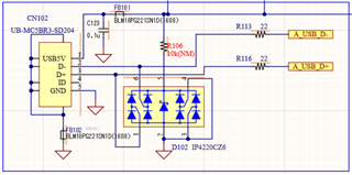
           USB connected and VBUS rises to 5V.                 CPU Vdd3.0V is power off until the switch will be turned ON.

But to protect CPU pin over voltage, I would like to add TS3USB31 USB

bus switch for CPU protection.
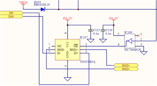
Could you tell me Is this measure needed for this matter ?

I guess this countermeasure is too complicated.

How about is this issue do you think ?

Your help is highly appreciated.

Best regards,

Yoshiaki Maehara

  • Maehara-san,

    The expert on this device is out in vacation and will return next week, thus he might have additional insights about your design. 

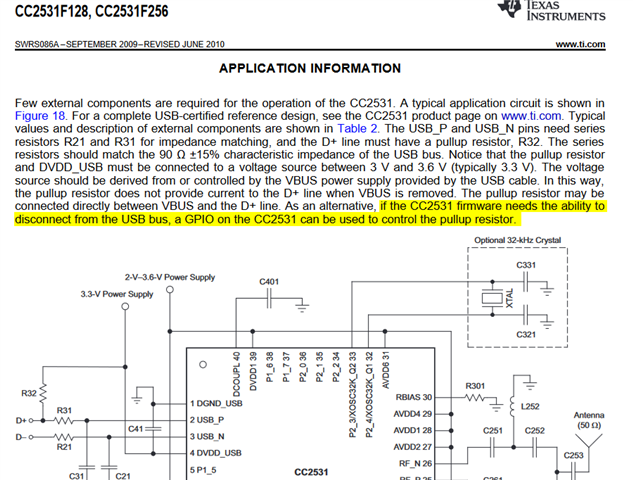
    I have a few comments. If I understood correctly your question in your old post, the CC2531 device can operate plugged without damaging it. The reason for my conclusion is the Application Information description in its datasheet, which talks about the scenario where the device remains plugged to the USB lines but can be disconnected by controlling the pull up resistor in the DP line.

    However, if your product is in an environment where there is a risk of having very harsh electrical noise, then the use of a protection switch can be a safer option as it disconnects the data lines (DP/DM). However, if you are concerned also in protecting the VBUS voltage line, you will have to design your power supply section with protection for the supply line as well.

    Hope this helps,

    Rafael

  • Hi, desouza-san,

    Thank you very much for your warm reply.

    I also re-reading the CC2531 datasheet again and again, the explanation that you pointed.

    But unfortunately somehow I guess it describes when USB is connected and CPU is working, how to disconnect the USB from host controlling 1.5k pull up resister by GPIO.

    It maybe describes CPU is powered on situation I guess, right ?  Maybe my English explanation was poor.

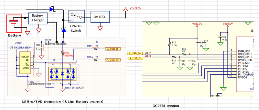
    Therefore, I had rewrited the block diagram of our system.

    This system operation is shown below,

    1. When USB is just connected, a LIPO Battery would continue charging.(system is powered off)

    2. Then, switch is turned on, the system include CC2531 will be working.
    (1.5kΩ pullup is also powered on, then USB HOST connect to the CC2531)


    3. If USB is disconnected , the Lipo battery will be supply system power.

    We are concerning under the 1. condition, CC2531 DP and DM pin is connected in spite of IC is powered down.

    As shown, we are adding USB data line and VBUS serge protection with D102 IP4220CZ6.

    ...

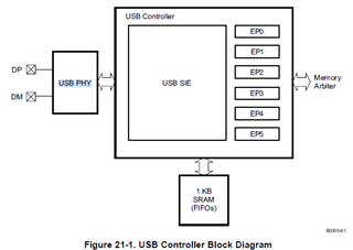
    BTW, in TI SWRU191F technical manual, CC2531 DP PM pin is connected to USB PHY circuit.

    I guess it may consisted with driver and reciever circuit, so it would be different from other GPIO absolute input voltage. (When CC2531 power down, over 0.3V is prohibited)

    If it is similar to RS485 PHY IC, I guess it wouldn't damaged even if some power off nodes are connected with signal is busy.

    Is my understanding is correct ?

    And if you could,  could you show me the USB PHY schematics and electrical specification?

    CC2531 Electrical specification for GPIO

    Drawings: some of  USB 2.0 PHY schematics

    I'm sorry for poor English and explanation.

    I would like to abolish TS3USB31 if the USB PHY is strong enough for this situation.

    Anyway, I would like to wait the expert person will return from vacation.

    Thank you very much for all of your usual kind support.

    I would like to wait for your additional assistance.

    Best regards,

    Yoshiaki Maehara

  • Hi, desouza-san and other Ti support team.

    Unfortunately, I haven't gotten additional advice until now.

    Could anyone help me about this issue ?

    Best regards,

    Yoshiaki Maehara