This thread has been locked.

If you have a related question, please click the "Ask a related question" button in the top right corner. The newly created question will be automatically linked to this question.

CC2652P: CC2652 maximum range distance

Part Number: CC2652P
Other Parts Discussed in Thread: SIMPLELINK-CC13XX-CC26XX-SDK, SYSCONFIG, Z-STACK

Hi TI!

I have a design with CC2562P. The design has the a similar antenna attached (3dbi)

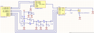
The RF shematic is attached. 

The anntena connector is very near of C10 U13 - U12 - CC2652 (1 cm) to avoid matching problems. 

I am using the power amplifier (PA). RF front end: Internal differencia  bias.

The máximun range distance is about 20-30 mtrs, which is very short.

What I could do to increase the range.

What could be the cause of such a short range?

Thank you very much. 

Best Regards. 

  • Hi albgarc2014,

    Are you using SIMPLELINK-CC13XX-CC26XX-SDK v6.30 zc_generic like from your previous E2E thread to perform this test?  Have you set the SysConfig -> Zigbee -> Radio -> Transmit Power to 20 dBm?  I also recommend testing with SmartRF Studio 7 and comparing range performance.  Your PA output design appears to be directly based off of the LAUNCHXL-CC1352P-2, however it would still be a good idea to submit your design to SIMPLELINK-2-4GHZ-DESIGN-REVIEWS for further review.

    Regards,
    Ryan

  • Hi Ryan
    I am using SIMPLELINK-CC13XX-CC26XX-SDK v4.10 zc_generic.

    With v6.3 I have not been able to customize the project to put RF front end on internal differential bias.

    I am using 16 dbm, if I increase it it seems that the CC2652 resets.

    Any idea?

    Thanks

  • You should be using the latest SDK version, and RF Design settings will be fully configurable after selecting the "Use Custom Board" option.  Make sure that the VDDR is forced from within the Device Configuration.  Make sure that a LAUNCHXL-CC1352P-2 design is referenced.

    Regards,
    Ryan

  • Hi Ryan, 

    I have the examples projects from the last SDK and I can customize it. But the same result. 

    For me it is sure that the problem is with the power amplifier. With 5dbm power (without amplifier) I have even more range than with the amplifier (> 14 dbm). Even if I compare with the Launch Pad range at 5bm, I'm doing very well.

    So my problem is with the power amplifier.

    For me my problems can be these:

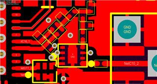
    1-) Impedance coupling. However the distance the signal travels is very small so it should not be a problem (see attached pictures).

    2-) The angle that the signal tracks travel from the amplifier (see attached pictures). However on the P2 launch pad, there are 2 angles of 90 and it works perfectly on the launch pad.

    Do you consider that any of these could be the problem? Or do you think it could be something else? Please check the attached image.

  • Do you have multiple custom boards to test with, and have you tried performing range tests with SmartRF Studio?  I will loop in a HW expert to further comment on the design.

    Regards,
    Ryan

  • Hi Ryan!

    Thanks very much.

    Yes, I have multiple custom boards. The same for all custom boards.

    About SMart RF, no yet. 

    Thanks very much for the HW expert.

  • Testing with SmartRF Studio may help us determine whether it's a custom hardware build or Z-Stack software configuration issue.

    Regards,
    Ryan

  • Hi albgarc2014,

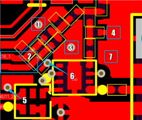
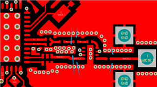
    I can chime on this but without seeing the full layout it is difficult to tell where the problem lies. Based off the layout image, there are few issues I spotted.

    1. Shunt components need immediate access to ground otherwise unwanted inductance will affect RF tuning

    2. The bottom line of the balun is slightly longer than the top line. They should be equal.

    3. Needs more ground vias

    4. This shunt components need a ground via as close as possible to its ground pad

    5. This ground vias seems to be outside the ground plane

    6. Without an immediate ground plane, this ground via will add additional unwanted inductance

    7. We recommend adding via fencing along the edges of the ground plane to isolate the RF signal from other parts of the board. See Example Below:

  • Hi Ryan, Bun Kuch, 

    Sincerely thank yuo very much. 

    I think that the layauot's pointing out is my problem.
    I will come back with some questions and then close the thread.

    Thanks very much. 

    Best regards

  • Hi Ryan, Bun Kuch, 

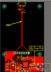
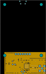
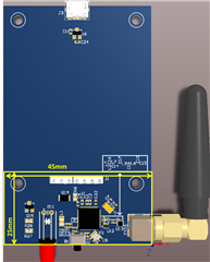
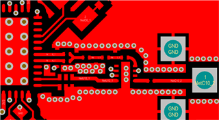
    I have redesigned the RF front end according to Bun Kuch's suggestions.  But I have a few points that I would like to confirm if they are correct or no. 

    1-) The trace of gnd (before the solid polygon of gnd) shown in picture 1 can be a problem? See picture 1.

    2-) Is the area of the solid gnd polygon (25mm x 45mm) OK for the antenna? See pictures 2 and 3.

    3-) Is the routing of the RF signals correct? See picture 4.

    4-) As the RF traces are short, there should be no problem with impedance coupling, am I right?

    Picture 1:

    Picture 2:

    Picture 3: 

    Picture 4:

    Sincerely, Thanks very much. 

  • Please be patient as the SimpleLink hardware experts are on leave until January 3rd.  Formal hardware design reviews can be submitted through SIMPLELINK-2-4GHZ-DESIGN-REVIEWS but will have a similar wait time.  Please provide full schematics and board layout for the most effective review.  You can reference the LAUNCHXL-CC2652P-2 Design Files and SWRA640 to further identify any other reasons for failure.

    Regards,
    Ryan

  • Hi Alberto,

    My teammate is currently reviewing your design, but I will answer your questions here too so there may be some overlap.

    1. I do not recommend a ground trace as it tends to create undesirable effects. I would suggest filling those "voids" with solid ground planes.

    2. Yes, assuming suggestion #1 is implemented.

    3. Please match the gap width and ensure that the RF traces are 50 ohms.

    4. Should not be a problem.

    Best regards,

    Bun