This thread has been locked.

If you have a related question, please click the "Ask a related question" button in the top right corner. The newly created question will be automatically linked to this question.

Reading ADC Sensor value

Other Parts Discussed in Thread: Z-STACK, CC2530, CC2530EM

Now i have familiar with Sensor Demo. If I want to use external Sensor with Gpio. I have gone through Some Doc. Steps For Reading External sensor.

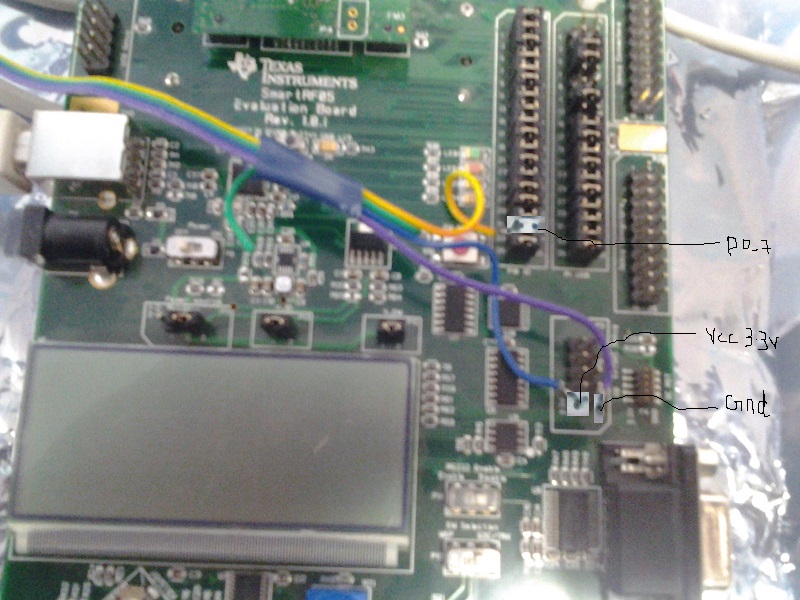
1)Connect sensor output to any digital i/o pin( P0_0 - P0_7). I found that, P0_7 is connected to pin 17. But in Smart RF 05 EB, there is two pin 17. one is P10 IO and P1 USB. Which should i have to connect?

2)Configure that pin as input pin.

for example i am P0_7,

P0SEL = 0x00;

P0DIR = 0x00;

APCFG = 0x80;(In which file of z-stack this SFR defined ?????)

3)HalAdcSetReference( HAL_ADC_REF_125V );

      adc_value =  HalAdcRead( HAL_ADC_CHN_AIN6, HAL_ADC_RESOLUTION_12 );

where adc_value in uint16.

These 3 step is enough, or need some more steps?


  • The followings are my steps:

    1. The P0.7 is on P10 pin 33 on SmartRF05EB so you need to input analog signal from here.

    2. Use the following codes to read ADC value. Here I set ADC reference to HAL_ADC_REF_125V which means that max measurable voltage from P0.7 is 1.15V.

    uint16 adc_ain7=0;

    HalAdcSetReference(HAL_ADC_REF_125V);
    adc_ain7=HalAdcRead(HAL_ADC_CHN_AIN7,HAL_ADC_RESOLUTION_10);

  • Thanks for your reply, No need of point 2, which i have mentioned in my previous post. Then how it can act that pin as input pin or output pin.

  • You can refer to swru191 section 7.6.7 Operational Amplifier and Analog Comparator which says,

    The settings in the APCFG register override the settings in P0SEL.

  • I understand, but little confuse, what does it mean "The settings in the APCFG register override the settings in P0SEL." . It also says we need to set a corresponding bit as 1 for input in APCFG Register, which means APCFG = 0x80; in my case??

    So, in the step 2, i need just APCFG = 0x80;(if yes, where it is defined in zstack).

  • Yes. In ZStack ADCCFG is APCFG.

  • I am having a sensor, which will read a temperature and Humidity. In which 16-bit will be Humidity Data(8-bit interger and 8-bit decimal) and next 16-but will be Temperature Data(8-bit interger and 8-bit decimal) and 8-bit check sum.

    The microcontroller program will be.

    for (i=0; i<5; i++)
    buf[i] = Read_Sensor();

    where buf[0] = Humidity int value
    buf[1] = Humidity Decimal value
    and so on...
    Serial_Transmit("Humidity = ");
    Serial_Transmit( buf[0], em);
    Serial_Transmit(".");
    Serial_Transmit( buf[1], em);
    and so on...


    If i use Zigbee for this, I used like this,

    for(i=0 ; i<5; i++)
    {
    buf[i] = HalAdcRead(HAL_ADC_CHN_AIN7,HAL_ADC_RESOLUTION_10)
    }
    I have created Different Cluster for Temperature and Humidity Sensor. But how can i send a data. I mean one buf is for Interger and other is Decimal.
    I can't Send like this af_SendData(........,hum cluster_id, ....., buf[0],...);
    af_SendData(........,hum cluster_id, ....., buf[1],...);

    Any suggestion.

  • I have no idea how you can use HalAdcRead to read integer and decimal part of temperature and humidity. As I know, there is no sensor of this kind interface. Are you sure you can do this?

  • I mean that sensor is giving 40-bit data if MCU triggers, Since HalAdcRead will written 16-bit Data. Then How can i read 40-bit Sensor Data.

  • Would you specify what sensor model will give you 40 bits data? I never heard of that. Anyway, the reading output should be converted to Celsius then transmit by ZCL command.

  • here the datasheet of sensor5127.sen11301p.pdf

    HalAdcRead will return 16-bit data. 

    Can i do like this

    uint16 sen[2] = {0,0}

    sen[0] = HalAdcRead(HAL_ADC_CHN_AIN7,HAL_ADC_RESOLUTION_10); (->Humitidity value)

    sen[1] = HalAdcRead(HAL_ADC_CHN_AIN7,HAL_ADC_RESOLUTION_10);(->Temperature Value)

    i)if i do this then, it will give a error, since

    typedef struct
    {
    uint16 attrID; // atrribute ID
    uint8 dataType; // attribute data type
    uint8 *attrData; // this structure is allocated, so the data is HERE
    // - the size depends on the data type of attrID
    } zclReport_t

    whether i need change that as uint16 *??

    ii)One more thing i need to ask, you told P0_7 is connected to P10 pin 33. But this Schematic 8863.0724.CC2530EM_1_3_1_discrete_schematic.pdf indicates P0_7 is connected to pin 17 of P1 USB. I didn't from the schematic where the vcc and ground is connected

    Can you clarify my simple doubts


  • 1. From your sensor datasheet, it doesn't output analog signal so you shouldn't use ADC to read sensor data. I looks more likely that you should use GPI to read it. There are already example codes inside data sheet.

    2. p0_7 of CC2530 EM is connected to P10 pin 33 on SmartRF05EB. You need to read schematics of SmartRF05EB too.

  • 1)That code is for Aurdino board and seeeduino mega. I am not aware of that. I worked only on 8051 and PIC. In that code they are using _BV, what does it mean. I understand only the read_dht11_dat()  function. For programming cc2530, How to do i read instead of HalAdcRead?. 

    2)Yes, I have Seen the Schematic of SmartRF05EB. Whether my understanding is correct, In the schematic of CC2530, P0_7 is connected pin 17.  In the SmartRF the pin 17 is named as EM_POT_R in the table 2:- EM connector P5 pin-out. That EM_POT_R is connected to Pin 33 of P10.

    3)What is - EM connector P5 pin-out means it is the pins of P10? and - EM connector P6 pin-out means pins of P1 USB?

  • 1. The document is not detail enough so I can't help anymore. I would suggest you to contact the manufacture to get more precise user manual.

    2. It is obvious in schematic. I don't see what your problem now.

  • 1)If it is giving binary data. Just i want to read the data, What should i do?

    2) In this schematic 2766.SmartRF05EB_1_8_1_Schematics.pdf pin 33 connected to EM_POT_R. No where is indicating for P0_7. P0_0 is connected to pin 7 in P10? where the Vcc and Ground is connected??. I getting confuse to refer. Is there any table for pin connection? where i can find P0_7 is connected to pin 33 and P0_0 is connected to Pin7

  • 1)Here the datasheet 1007.DHT11.pdf Could help me, how to read the data.

    2)2) In this schematic 2766.SmartRF05EB_1_8_1_Schematics.pdf pin 33 connected to EM_POT_R. No where is indicating for P0_7. P0_0 is connected to pin 7 in P10? where the Vcc and Ground is connected??. I getting confuse to refer. Is there any table for pin connection? where i can find P0_7 is connected to pin 33 and P0_0 is connected to Pin7.

  • 1. This data sheet is clear enough for programming and you should do that by yourself.

    2. P0_7 is pin 17 on P1 in CC2530EM schematic and P1 is connected to P5 which is on SmartRF05EB schematic. In SmartRF05EB schematic, Pin 17 of P5 is labeled to EM_POT_R and it is directly connected to pin 33 on P10 if you search keyword "EM_POT_R" in the schematic.

  • 1) This sensor is giving binary data's(10110...). first read will give humidity data, Second read will give temp..  I just want to read a data's from GPI. I used this sensor in 8051 and PIC micro controller.  But i don't to how read in CC2530. Simple question is How can i  read a data from GPI?

    2)Yes, i got it. Then P0_0 is connected to pin 7 of P10, am i right? what about ground and Vcc?? 

  • 1. The following example show you how to use P0_7 as GPI

    P0SEL &= (~BV(7)); //Config P0_7 to GPIO function

    P0DIR  &= (~BV(7)); //Config P0_7 to GPI

    GPI_P0_7 = P0_7; //Read GPI from P0_7 directly.

    2. No, P0_0 is connected to pin 5 of P10. GND and Vcc is obvious on schematic. What is your problem about GND and Vcc

  • 1) After setting

     POSEL &=  ~(1 << 7)

    PODIR &= ~(1 << 7)

    i didn't get this line GPI_P0_7 = P0_7, 

    You mean uint8 data = P0_7;

       We can directly write as P0_7? 

    2)I didn't find gnd and VCC in Schematic. Can you tell me where it is connected. I am sorry for basic and simple Question, please clarify my doubt. 

  • 1. Yes, you can directly read/write as P0_7 and it is defined in ioCC2530.h.

    2. VCC is on pin 7 and pin9 of P6 and pin 1 and pin 19 of P5 on SmartRF05EB. It is all in SmartRF05 Evaluation Board User’s Guide. Do you really read it?

  • Yes i have seen that in the Table, But i didn't get in the Schematic. I traced for VCC and gnd in Schematic, I found VCC_EM. which is connected to Power supply. I want to connect the Sensor's VCC and GND wire to SmartRF, I found Three gnd in Smart Rf EB, which i marked in Pic  

    Can i directly solder a wire in that? Earlier i used Developing board, Which i used do in General PCB. So i request to guide me. Where i can find VCC to connect 3.2v to Sensor.

  • You can use VCC_EM directly. It is on P15.

  • Thanks a lot, One last Question.

    1)As you told i can use VCC_EM directly, There is two pin,pin 1 and 2. I can solder a vcc sensor wire in either pin, right?

    2)And i can solder gnd sensor wire to either 3 side as i mentioned in Picture of last Post??

    Thanks once again

  • Yes for both.

  • Sorry for disturbing you again, Really i need your help. As per my Understanding  of Sensor.

    The MCU initiates data transmission by issuing a “Start” signal. The MCU first pulls the data line low for at least 18 ms and then pulls it high for next 20-40 μs. When the line is released by the MCU the sensor responds to the “Start“ signal by pulling the line low for 80 μs followed by a logic high signal that also lasts for 80 μs. Remember that the MCUpin must be configured to input after finishing the “Start“ signal. Once detecting the response signal from the sensor, the MCU is ready to receive data from the sensor. The sensor then sends 5 bytes of data continuously in the data line with the most significant bit first for each byte. The 5 bytes of data consists of,

    Data = Integer Byte of RH + Decimal Byte of RH + Integer Byte of Temp. + Decimal Byte of Temp. + Checksum Byte

    For DHT11 sensor, the decimal bytes of temperature and humidity measurements are always zero. Therefore, the first and third bytes of received data actually give the numeric values of the measured relative humidity (%) and temperature (°C). The last byte is the checksum byte which is used to make sure that the data transfer has happened without any error. If all the five bytes are transferred successfully then the checksum byte must be equal to the last 8 bits of the sum of the first four bytes

            In order to send a bit of data, the sensor first pulls the line low for 50 μs and then raises it to high for 26-28 μs (for sending “0″), or for 70 μs (for sending “1”). So the width of the positive pulse carries information about 1 and 0.

            At the end of the last transmitted bit, the sensor pulls the data line low for 50 μs and then releases it. It is now ready to receive another start signal from the MCU.

               I have done this program using PIC microcontroller. 

    // LCD module connections
    sbit LCD_RS at RB2_bit;
    sbit LCD_EN at RB3_bit;
    sbit LCD_D4 at RB4_bit;
    sbit LCD_D5 at RB5_bit;
    sbit LCD_D6 at RB6_bit;
    sbit LCD_D7 at RB7_bit;
    sbit LCD_RS_Direction at TRISB2_bit;
    sbit LCD_EN_Direction at TRISB3_bit;
    sbit LCD_D4_Direction at TRISB4_bit;
    sbit LCD_D5_Direction at TRISB5_bit;
    sbit LCD_D6_Direction at TRISB6_bit;
    sbit LCD_D7_Direction at TRISB7_bit;
    
    sbit Data at RA0_bit;
    sbit DataDir at TRISA0_bit;
    char message1[] = "Temp = 00.0 C";
    char message2[] = "RH   = 00.0 %";
    unsigned short TOUT = 0, CheckSum, i;
    unsigned short T_Byte1, T_Byte2, RH_Byte1, RH_Byte2;
    
    void StartSignal(){
      DataDir = 0;     // Data port is output
      Data    = 0;
      Delay_ms(25);
      Data    = 1;
      Delay_us(30);
      DataDir = 1;     // Data port is input
    
    }
    
    unsigned short CheckResponse(){
      TOUT = 0;
      TMR2 = 0;
      T2CON.TMR2ON = 1;      // start timer
      while(!Data && !TOUT);
      if (TOUT) return 0;
      else {
       TMR2 = 0;
       while(Data && !TOUT);
       if (TOUT) 
         return 0;
       else {
        T2CON.TMR2ON = 0;
        return 1;
       }
      }
    }
    
    unsigned short ReadByte(){
      unsigned short num = 0, t;
      DataDir = 1;
      for (i=0; i<8; i++){
       while(!Data);
       TMR2 = 0;
       T2CON.TMR2ON = 1;
       while(Data);
       T2CON.TMR2ON = 0;
       if(TMR2 > 40) num |= 1<<(7-i);  // If time > 40us, Data is 1
      }
      return num;
    }
    
    void interrupt(){
      if(PIR1.TMR2IF){
       TOUT = 1;
       T2CON.TMR2ON = 0; // stop timer
       PIR1.TMR2IF  = 0; // Clear TMR0 interrupt flag
      }
    }
    
    void main() {
      unsigned short check;
      TRISB = 0b00000000;
      PORTB = 0;
      TRISA = 0b00100001;
      CMCON = 7;
      INTCON.GIE = 1;    //Enable global interrupt
      INTCON.PEIE = 1;   //Enable peripheral interrupt
      // Configure Timer2 module
      PIE1.TMR2IE = 1;  // Enable Timer2 interrupt
      T2CON = 0;        // Prescaler 1:1, and Timer2 is off initially
      PIR1.TMR2IF =0;   // Clear TMR INT Flag bit
      TMR2 = 0;
      Lcd_Init();
      Lcd_Cmd(_Lcd_Clear);
      Lcd_Cmd(_LCD_CURSOR_OFF);
    
      do {
        Delay_ms(1000);
        StartSignal();
        check = CheckResponse();
        if (!check) {
         Lcd_Cmd(_Lcd_Clear);
         Lcd_Out(1, 1, "No response");
         Lcd_Out(2, 1, "from the sensor");
        }
        else{
        
         RH_Byte1 = ReadByte();
         RH_Byte2 = ReadByte();
         T_Byte1 = ReadByte();
         T_Byte2 = ReadByte();
         CheckSum = ReadByte();
         // Check for error in Data reception
         if (CheckSum == ((RH_Byte1 + RH_Byte2 + T_Byte1 + T_Byte2) & 0xFF))
         {
          message1[7]  = T_Byte1/10 + 48;
          message1[8]  = T_Byte1%10 + 48;
          message1[10] = T_Byte2/10 + 48;
          message2[7]  = RH_Byte1/10 + 48;
          message2[8]  = RH_Byte1%10 + 48;
          message2[10] = RH_Byte2/10 + 48;
          message1[11] = 223;     // Degree symbol
          Lcd_Cmd(_Lcd_Clear);
          Lcd_Out(1, 1, message1);
          Lcd_Out(2, 1, message2);
          }
          
          else{
           Lcd_Cmd(_Lcd_Clear);
           Lcd_Out(1, 1, "Checksum Error!");
           Lcd_Out(2, 1, "Trying Again ...");
          }
        }
    
      }while(1);
    }
    . It's very easy and understandable code. In this i Need to set port as i/o and the pin. But in CC2530, we care about only pin. If u did have any doubts in this program, i will clarify. So don't let me as. I need help from you


  • 1007.DHT11.c is mapped to the sensor datasheet without problem and you can try to porting it to CC2530. What help do you need from me?

  • I have ported to cc2530. But it doesn't work. At first time Coordinator displays Junk value, Then it is not showing any thing. Will you check my code, Did i done some mistake. 

    static void zclSensor_Status( void )
    {
    zclReportCmd_t reportCmd;

    uint8 i;
    P0SEL &= ~(1<<7);//make gpio
    /*Start a signal*/
    PODIR |= (1<<7);//make output port
    P0_7 = 0;
    delay(18);
    P0_7 = 1;
    delay_microsec(40);
    P0DIR &= ~(1<<7);

    /*Check the response*/
    while(!P0_7); //wait till sensor make this line as low
    delay_microsec(80);
    while(P0_7); //wait till again it makes high
    delay_microsec(80);

    /*Start receving a data*/
    for(i=0; i<5; i++)
    {
    Sensor_Value[i] = read_data();
    }

    reportCmd.numAttr=1;

    reportCmd.attrList[0].attrID = ATTRID_MS_TEMPERATURE_MEASURED_VALUE;
    reportCmd.attrList[0].dataType = ZCL_DATATYPE_INT8;
    reportCmd.attrList[0].attrData = Sensor_Value;
    zcl_SendReportCmd( TempSensor_ENDPOINT, &zclTempSensor_DstAddr,
    ZCL_CLUSTER_ID_MS_TEMPERATURE_MEASUREMENT, &reportCmd,
    1, 0, 1 );

    /*Sensor data*/
    uint8 read_data()
    {
    uint8 i = 0;
    uint8 num = 0;
    for(i=0; i<8; i++)
    {
    while(!P0_7); //wait till line makes low
    if(P0_7)
    num |= (1 << (7-i));
    while(P0_7);
    }
    return num;
    }


    }

  • Do you program 1007.DHT11.c? TMR2 is set to 0 and started when GPI Data gets rising edge. While GPI Data turns to low, the TMR2 stops and it check the duration of GPI Data at high state. If it is larger than 40 us, set the bit to 1. Otherwise, set the bit to 0. However, you don't start a timer when GPI P0_7 gets rising edge. Of course, you also don't stop is and calculate the duration that GPI P0_7 keeps at high status. So, you won't get correct data from sensor. Try to revise your read_data for CC2530 and it should work.

  • 1) Activating a timer in PIC is easy and i know, But how to activate timer for CC2530 which will count how much time it took in microSecond or milliSecond

    2)And if you see code, I have created a delay function with simple for loop, which for PIC micro controller, Is there any standard delay function for microsecond and millisecond in CC2530.

    I think am last stage. So can you guide.

  • There is a API halMcuWaitMs which can delay micro seconds in CC2530. You can use it inside your read_data to achieve similar function in PIC. When you want to use it, you need to do "extern void halMcuWaitMs(uint16 msec);" in your code.

  • Thanks again, 

    1) halMcuWaitMs is for delay in micro second or milliSecond.

    2)You can use it inside your read_data to achieve similar function in PIC

         In the read_data i have to use a timer which will count time, Then only i will come to know how much time it took for reading Data. In PIC T2CON.TMR2ON = 1; this will start timer and TMR2 will get increment till it stops T2CON.TMR2ON = 0; This same timer SFR is using in CC2530?this you mean?


  • 1. It is for delay micro seconds.

    2. I would do something like the followings:uint8  short ReadByte(){
      uint8 i;
      uint8 num = 0;
      uint8 us = 0;
      P0DIR &= (~BV(7)); //Set P0_7 to GPI
      for (i=0; i<8; i++){
       while(!P0_7);
       us = 0;
       while(P0_7)
       {
               halMcuWaitMs(2);
               us+=2;
       }
       if(us > 40) num |= 1<<(7-i);  // If time > 40us, Data is 1
      }
      return num;
    }

  • It is giving undefined reference to halMcuWaitMs. Where it is defined in Zstack?. 

  • Sorry, please use Onboard_wait() to replace halMcuWaitMs.

  • I facing a problem here

    /*Check the response*/
    while(!P0_7); //wait till sensor make this line as low
    delay_microsec(80);
    while(P0_7); //wait till again it makes high
    delay_microsec(80);

    After sending Desc Rsp send, ZC is waiting for ZED response, Then i start to Debug, till start signal by CC2230 is running fine. Even in the Check response P0_7 goes low, then CC2530 waiting till P0_7 high, But unfortunately it is not happening. my Connection of Sensor is  

    Sensor operates from 3.5 - 5V. I think it can work in 3.3V also. Whether this is causing problem for me? If Yes how can get 3.5V in SmartRf board.

  • 1. I suggest you to use scope to monitor signal on P0_7 and see if it matches sensor data sheet.

    2. There isn't  any power pin can supply 3.5V-5V on SmartRF05EB. I would suggest you to use external power source if you need it. 

  • What do you mean by, to use scope to monitor signal on P0_7?, i didn't get this. Can you please elaborate. what should i do?

  • What I mean scope is oscilloscope. Use it to watch the signal on P0_7 and see if it matches the requirements on sensor datasheet.

  • Hi,

    1.) i have a similary problem. I use the CC1111 and the ADC for reading the temp. over an extern Sensor. But if i config. a P0 Pin over ADCCFG the other P0SEL configuration will overwrite. But i need the other P0 Pins for other things. 

    How can i configurate this issue?

    2.) ADCCFG configuration makes a P0 Pin to a analog input? Is that right?

    Becouse i can not reas the Value which the Sensor gives. I use DMA for ADC. Maybe there is something wrong. Here some code:

    DMA config.:

    dma_p.SRCADDRH = ((uint16)&X_ADCL >> 8)& 0x00FF;
    dma_p.SRCADDRL = (uint16)&X_ADCL& 0x00FF;
    dma_p.DESTADDRH = (((uint16)&adc_data) >> 8)& 0x00FF;
    dma_p.DESTADDRL = ((uint16)&adc_data)& 0x00FF;

    dma_p.VLEN = DMA_VLEN_FIRST_BYTE_P_1;
    dma_p.LENH = 0;
    dma_p.LENL = 1;

    dma_p.WORDSIZE = DMA_WORDSIZE_BYTE;
    dma_p.TMODE = DMA_TMODE_SINGLE_REPEATED; 
    dma_p.TRIG = DMA_TRIG_ADC_CHALL;
    dma_p.SRCINC = DMA_SRCINC_1;
    dma_p.DESTINC = DMA_DESTINC_0;
    dma_p.IRQMASK = DMA_IRQMASK_DISABLE;
    dma_p.M8 = DMA_M8_USE_8_BITS;
    dma_p.PRIORITY = DMA_PRI_HIGH;

    DMA1CFGH = ((uint16)&dma_p >> 8) & 0x00FF;
    DMA1CFGL = (uint16)&dma_p & 0x00FF;

    ADCCFG |= ADCCFG_5; 

    DMAARM = DMAARM_CHANNEL1;

    adc = ADCL & 0xC0;
    adc |= (ADCH << 8);
    adc |= adc >> 6;

    temperature = (adc * 3300)/1023;
    temperature = temperature /100;

    U1DBUF = temperature;

    But i see only 00 on my UART or on my PC.

    What can be worng?

    Thanks