


Part Number: CC2530
Hello,
This is my first SPI connection and I have a trouble with my code. I can send and read data from the accelerometer adxl345, when a try to read the register 0x00, i expected 0xE5 but i receive 0xF2, i am using spi 4 wire connection, the SCLK work fine but i can't read correctly. I am using the below code:
#include "spi.h"

/**************************************************************************************************
 *                                           MACROS
 **************************************************************************************************/

#define XNV_SPI_BEGIN() st(P1_3 = 0;)
#define XNV_SPI_TX(x) st(U1CSR &= ~0x02; U1DBUF = (x);)
#define XNV_SPI_RX() U1DBUF
#define XNV_SPI_WAIT_RXRDY() st(while (!(U1CSR & 0x02));)
#define XNV_SPI_END() st(P1_3 = 1;)


// The TI reference design uses UART1 Alt. 2 in SPI mode.
#define XNV_SPI_INIT() \
st( \
  /* Mode select UART1 SPI Mode as master. */\
  U1CSR = 0; \
  \
  /* Setup for 115200 baud. */\
  U1GCR = 11; \
  U1BAUD = 216; \
  \
  /* Set bit order to MSB */\
  U1GCR |= BV(5); \
  \
  /* Set UART1 I/O to alternate 2 location on P1 pins. */\
  PERCFG |= 0x02;  /* U1CFG */\
  \
  /* Select peripheral function on I/O pins but SS is left as GPIO for separate control. */\
  P1SEL |= 0xE0;  /* SELP1_[7:4] */\
  /* P1.1,2,3: reset, LCD CS, XNV CS. */\
  P1SEL &= ~0x0E; \
  P1 |= 0x0E; \
  P1_1 = 0; \
  P1DIR |= 0x0E; \
  \
  /* Give UART1 priority over Timer3. */\
  P2SEL &= ~0x20;  /* PRI2P1 */\
  \
  /* When SPI config is complete, enable it. */\
  U1CSR |= 0x40; \
  /* Release XNV reset. */\
  P1_1 = 1; \
)

void halMasterSpiInit(void)
{
  XNV_SPI_INIT();
}// halMasterSpiInit


uint8 higherbyte;
uint8 lowerbyte;
uint8 spiRead(uint8 addr)
{
    uint8 data = 0;

    XNV_SPI_BEGIN(); // begin transmission

    XNV_SPI_TX(addr); // send addr
    for(uint8 i = 0; i < 4 ; i++) {
      XNV_SPI_WAIT_RXRDY(); //wait till received byte is ready

      higherbyte = XNV_SPI_RX(); // copy received byte

      XNV_SPI_WAIT_RXRDY(); //wait till received byte is ready

      lowerbyte = XNV_SPI_RX(); // copy received byte
    }
    XNV_SPI_END(); // End transmission

    data = higherbyte;
    return (data);
}


// Transmit code

void spiWrite(uint8 addr,uint8 higherbyte/*![0], uint8 lowerbyte*/)
{
    XNV_SPI_BEGIN(); // begin transmission

    XNV_SPI_TX(addr); // send addr

    XNV_SPI_TX(higherbyte); //send higher byte

    //![0]XNV_SPI_TX(lowerbyte); //send lower byte

    XNV_SPI_END(); // End transmission
}
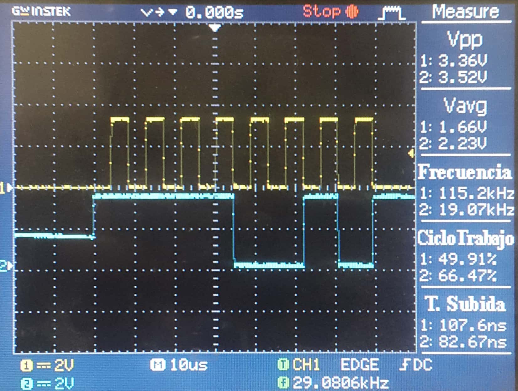
The yellow signal is the SCLK and the blue signal is the MISO
Please any help and thanks a lot,
Best Regards

