This thread has been locked.

If you have a related question, please click the "Ask a related question" button in the top right corner. The newly created question will be automatically linked to this question.

LME49830 unstable issue

We configure LME49830 to a non-inverting amplifier in DC-coupled setting to drive a capacitive loading which is almost 340nF.

Actually we use this design to drive a 340nF MLCC capacitance  as a dummy loading.

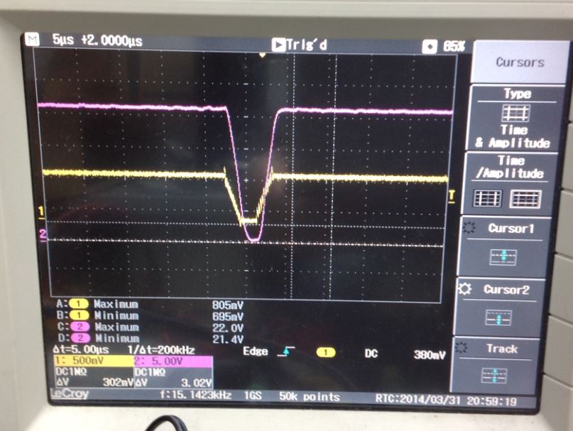
But we find the unstable oscillation shown in below picture...

CH1(yellow) is input signal.

CH2 (magenta) is output signal.

CH3 (cyan) is output current.

We  change the compensation (Ccomp) capacitance from 60pF to 100pF. With this help it can remove oscillation,

but the slew rate is not sufficient neither 60pF nor 100pF condition. 

We can't find a combination to satisfied slew rate of 25V/us above.

Is there any recommendation?

Following is the schematic.

  • Hi, Po-Chen,

    I suspect the problem is the layout and decoupling of the half-H-bridge. If this loop isn't extremely tight, you will have problems.

    You might try increasing the gate resistors to slow down the switching edges which might help.

    -d2

  • Hi Don,
    I increase the gate resistors to a higher value is not help,
    the unstable oscillation can't be eliminated.
    I try to increase the output series to a large value 0.33~1 Ohm,
    change the compensation Cap to a high Q Cap and increase the gain can fix it.
    But it still can't meet our requirment.

    And I finally found the Vgs waveform of MOSFET is so bad.
    The falling edge is too slow, the rising edge is too fast.
    How can I handle that?

    (A)I remove the bad trace from PCB


    (B)Minimize the glitch, is it good enough?


    (C)Yellow - Input waveform rising edge 2us, hold time 2us, falling edge 2us, Vp-p 0.8V
    Pink - Vgs of MOSFET
    Loading 330nF Cap

    (D) Yellow - Input waveform
    Pink - Vgs of MOSFET
    No Load


    (E) Yellow - Input waveform
    Pink - Output waveform Vp-p 18V
    No Load

  • Hello Po-Chen-san,

    I'll suggest you couple of thing to have stable output with your C Load condition 340nF Cap load as follow.

    Onyour schematic doesn't have decoupling cap on Vee side. So you should have decoupling cap as close as device pin and Power tr. To get 25V/us of Slew rate, put about 15pF as Cc.  Put 1 ohm resistor in seriese with CLaod as my schematic. And also put 6.8k as Rs to compensate DC offset on + Input pin and GND. Put Pwr Tr AB bias current setting Tr and resistor capacitor ckt ans set Iab on power Tr about 20mA. Then you will have stable output wave form I attached file.  Please visit following URL to check the schematic and output waveform.

    0003.Schematic & stability result.xlsx

    Best regards

    T NAOKAWA


  • I'd like to chime in here and suggest that a fundamental problem here is that the capacitance load needs a small series ballast resistor.  

    An amplifier's output impedance is established by its open-loop Z-out divided by its open loop gain. We know the loop gain falls with frequency, e.g., at -6dB/octave, so the closed-loop Z-out rises with frequency.  In fact, the output looks and acts like an inductor.  Adding a large capacitive load creates an L-C resonance, with a peak at the resonant frequency, Fres.  The O.P. needs to add a series resistor to his capacitor, of about Rs = 1 / 2 pi Cload Fres.  This resistor is located after the ampliifer's feedback connection point, and Rs Cload will set an upper -3dB response rolloff frequency for driving the capacitive load.  If this response-limit frequency is inadequate, other measures will be needed to reduce open-loop Z-out.

    Just to add a comment: Comparatively speaking, MOSFETs have a fairly low transconductance, e.g., compared to a BJT.  This creates a fairly high open-loop Z-out, that the LM49830 overcomes with its loop gain.  We shouldn't blame the the LM49830 for any troubles that ensue from the MOSFET's inadequacies.  :-)

    Cheers,

      - Win

  • Hi, Win,

    Thanks for taking time to join the conversation here! I look forward to seeing more posts from you in the Audio forums!

    -d2

  • Hi Win-san,

    Please take look at my post and my recommended schematic, I put 1 ohms resistor in seriese to cap load. Then I had good stability as shown in my picture.

    Best regards

    T NAOKAWA