This thread has been locked.

If you have a related question, please click the "Ask a related question" button in the top right corner. The newly created question will be automatically linked to this question.

TAS5760M: Power on/off Sequence of TAS5760M for hardware control.

Part Number: TAS5760M

Dear Sirs,

My customer asked us about Power on/off Sequence of TAS5760M for hardware control.

There is a phenomenon which is not output at power on of his board.
At that time, ANA_REG is 10 V and it is abnormal voltage. (Normal is 3.3V)
Therefore, I think that there is a factor in the power ON / OFF sequence.

Do you have what can be thought of as a cause in such a case?


His power on sequence is as follows.

1.After turning on the power supply, set SPK_SD to Low and SPK_SLEEP / ADR to High.
2.After the power supply is stabilized and the hard control pin is set, set SPK_SD to High.
3.After releasing shutdown, set SPK_SLEEP / ADR to Low and about 3 seconds after SPK_SD becomes High SPK_SLEEP / ADR is released.

Is this correct?

The power off sequence is
SPK_SD is LOW after SPK_SLEEP / ADR is HIGH and output OFF after the power is turned OFF.

Is this correct?


Best Regards,
Y.Hasebe

  • Hello Hasebe-san! I assume you are referencing the EVM? For hardware control mode are you using the default settings, or are you making any changes? It is important to make sure that the hardware control pins are set as defined in 9.4.1 Hardware Control Mode. Also, the sequence defined in 10.2.2.2.1 Startup Procedures- Hardware Control Mode is important, with all configurations and pins set prior to bringing up power:
    1. Configure all hardware pins as required by the application using PCB connections (that is PBTL, FREQ, GAIN, etc.)
    2. Start with SPK_SD pin pulled LOW and SPK_SLEEP/ADR pin pulled HIGH
    3. Bring up power supplies (it does not matter if PVDD/AVDD or DVDD comes up first, provided the device is held in shutdown.)
    4. Once power supplies are stable, start MCLK, SCLK, LRCK
    5. Once power supplies and clocks are stable and all hardware control pins have been configured, bring SPK_SD HIGH
    6. Once the device is out of shutdown mode, bring SPK_SLEEP/ADR LOW
    7. The device is now in normal operation

    Also, please also be aware that In Hardware Control mode, the device only operates in the 32, 48 or 64 x fS I²S modes, because it operates in Single-Speed Mode (SSM), which means that supported sample rates, MCLK rates, and
    SCLK rates are limited to those shown in the Table 3.

    thanks, Jeff
  • Hello Jeff-san,

    Thank you for your reply.

    I already had understood descriptions of datasheet.
    But I can't found actual timing chart.

    The sequence defined in 10.2.2.2.1 Startup Procedures:
    Is there a concrete time sequence of Startup Procedures?

    For example, we have the following description.
    2. Start with SPK_SD pin pulled LOW and SPK_SLEEP/ADR pin pulled HIGH.

    Is there any problem if this is done at the same time?
    Or is there no problem if SPK_SLEEP / ADR first goes HIGH then SPK_SD goes LOW?

    My customers are concerned about whether the time sequence is wrong.

    Please tell me if there is a specific time sequence.

    Best Regards,

    Y.Hasebe

  • Hello Jeff-san,

    Please give me some comment on the above question.

    Also, I have additional questions.

    For the customer power-up sequence, PVDD and AVDD are turned on with the same power supply,then DVDD is turned on.

    After that, a pulse of about 6 μs period is input for about 100 ms at 2 V pp at the terminal of SPK_SD.

    Is there a problem with this condition?

    Best Regards,

    Y.Hasebe

  • Hello Hasebe-san! Thanks for your patience. I have looped in Andy on your question. Thanks, Jeff
  • Hello Jeff-san,

    Thank you for your reply.

    I'm waiting for reply of Andy-san.

    Best Regards,

    Y.Hasebe

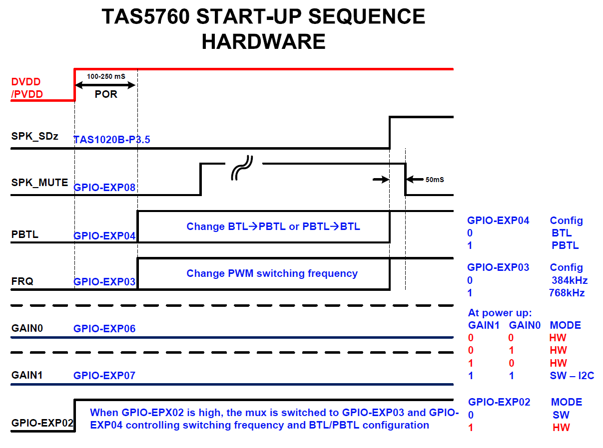
  • Hi Hasebe-san,

    Take a look at the following start-up sequence.

    Andy

  • Hello Andy-san,

    Thank you for your reply.

    I understand start up sequence.

    I have some questions.

    1.Is the POR (100 to 250 ms) shown in Sequence's diagram the time of RESET inside the IC?

    2.Is there a problem when a pulse waveform (logic of a certain period) is input to SPK_SD during the POR period?

     What problems can be considered if there is a problem?

    Best Regards,

    Y.Hasebe

  • Hello Andy-san,

    Could you please reply  to my previous additional questions?

    Best Regards,

    Y.Hasebe

  • Hello Andy-san,

    Could you please reply  to my previous additional questions?

    Best Regards,

    Y.Hasebe

  • See my comments below
    1.Is the POR (100 to 250 ms) shown in Sequence's diagram the time of RESET inside the IC?
    [Andy]: The POR is not due to the reset time of TAS5760. We add the POR time mostly due to system level requirements. For example, we want to make sure all the caps are fully charged and power supplies are stable.

    2.Is there a problem when a pulse waveform (logic of a certain period) is input to SPK_SD during the POR period?
    [Andy]: As I mentioned above, the start-up sequence is designed due to system level requirements. (eg. to avoid pop noise). The customer can try to pull high the SPK_SZ pin during the POR time, but they need to do tests to make sure no issue occurs by themselves.
  • Hello Andy-san,

    Thank you for your reply.

    I understand your comments.

    I will answer to my customer them.

    Best Regards,

    Y.Hasebe