Because of the Thanksgiving holiday in the U.S., TI E2E™ design support forum responses may be delayed from November 25 through December 2. Thank you for your patience.

This thread has been locked.

If you have a related question, please click the "Ask a related question" button in the top right corner. The newly created question will be automatically linked to this question.

OPA128 Debug

Other Parts Discussed in Thread: REF200, OPA131

HI,

I'm using OPA128 OPAMP for current source circuit with REF200, when i connect +15v supply to pin no 7 (+ Vcc) of OPA128 , i'm getting 13V at pin no 4 , i want to know the reason for this and i'm not getting correct output also, I want to know whether the OPA128 is in working condition or not . If OPA128 is not working properly pls suggest me an equivalent component as OPA128 is costly..... Expecting a speedy and positive reply.

Best regards . 

  • Karthik,

    Can you please provide a schematic of your circuit?  Please provide a description of what type of function you are trying to create.

    Regards, Bruce.

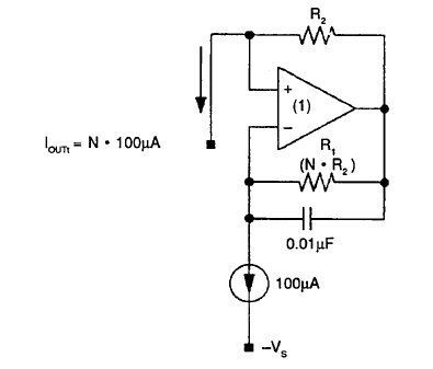
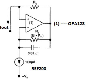
  • This is the circuit i'm using, i'm trying to generate constant 10 micro Amp current source. Initially circuit was functioning well and i got the output, but when i tried rebuild

    and check it, then i faced the problem, Vs given here is 15v and resistors R1 = 10 Kohm and R2 = 100Kohm. Pls help me solve the problem.


    Thanking you

  • Karthik,

    It is important to know how your negative power supply voltage is connected to the op amp (not shown in your schematic). Your original post indicated that the voltage on the negative supply pin (4) was 13V. This would seem impossible if pin 4 were connected to ground or some other power supply voltage. So the connections made to this pin are very important in diagnosing the problem.

    Also, your circuit does not show a load. What is the load and to what voltage is this load referenced?

    Regards, Bruce.

  • Hi,

    The circuit connections for OPA128 follows like this:

    Pin no (2): 10K ohm Resistor, 0.01 Micro farad Capacitor and input 100Micro amps from REF200

    Pin no (3): 100k Ohm Resistor

    Pin no(4): -15 V

    Pin no (5): NC

    Pin no (6): Feedback connection from pin no 2 &3

    Pin no(7): +15 V

    Pin no(8): GND

    The circuit was working properly for the 1st time. when i wanted to build it 2nd time i found the output from Pin no(3) was 38.86 micro Amp instead of 10 Micro amp, when i started debugging the circuit i found there was 13v in Pin no(4) before i connect it to source , I dono how 13v came before i connect it to source, at this time pin no(7) was connected to +15v. By looking at this i thought the incorrect output was because of damaged OPA128, But i'm not sure whether it its damaged or not. If u can help me find it is damaged or not it will be a great help.

    Best Regards.

  • Karthik,

    It appears that the op amp may be damaged. This may have occurred when you failed to connect the negative power supply. Did the output current change when you connected the negative power supply to pin 4?

    Bruce.

  • Hi Bruce,

    Yes, the output current was changed from 10 Micro-Amp to 38 Micro Amp. If the opamp is damaged , can u pls suggest me any suitable opamp of low cost with same performance or better performance. 

    Best regards.  

  • Karthik,

    Any op amp in the TO-99 metal package will be quite expensive.

    The OPA129 is much lower cost but uses the same IC internally. It is in an SO-8 package but has a non-standard pinout.

    The OPA131 is a lower cost op amp with similar behavior. Input bias current is significantly higher but okay for making a 10uA current source.

    Regards, Bruce

  • Hi, Bruce

    Thank you for your valuable response . 

    Best regards