Because of the holidays, TI E2E™ design support forum responses will be delayed from Dec. 25 through Jan. 2. Thank you for your patience.

This thread has been locked.

If you have a related question, please click the "Ask a related question" button in the top right corner. The newly created question will be automatically linked to this question.

OPA140 Impedance

Other Parts Discussed in Thread: OPA140, OPA130

Hi all,

Need advise on the input impedance portion of the OPA140. From the datasheet, it stated 10GOhm II 10pF at differential. Is the 10GOhm the internal resistance value II 10pF capacitance? So from there, can do some mathematical calculation to get the impedance value? Or the 10GOhm is already the impedance value at 10pF?
Engineer did a circuitry with 6Vs, however not able to get the measurement of 10GOhm. Kindly advise. Thanks.

  • Dear "All";

    The 10G ohms value is the resistive portion of the op amp input impedance. How did the engineer measure that 10G resistance? It isn't easy!

  •  

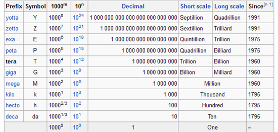
    The input impedance of OPA140 is actually 10T  (1012 = tera-ohm) and not 10G (109 = giga-ohm) but Neil is correct that this is a resistive part of the complex input impedance (see table below).


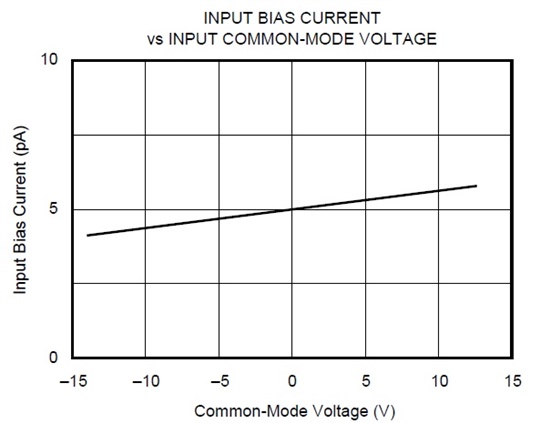
    The common-mode input resistance can be easily calculated using the IB vs Common-Mode voltage graph below: Rincm=30V/1.5pA =~2*1013 


  • Hi Neil, Marek,

    Thanks for the response.
    The engineer did the measurement by using an Ohmmeter. Measuring the IN- with respect to the V-, having measurement of ~250K. The idea is that the JFET input should have a very high resistance value or somewhat similar to the 1013. If the measurement is not from the JFET, please advise what is the 250K resistance measurement represents. Kindly advise. Thanks.

  • 123,

    You can NOT measure the impedance between the negative input and supply pin with an ohmmeter since it works by pushing its own test-current to determine the resistive value - this would corrupt the reading due to IB.  Of course, it is also beyond the point to measure the common-mode input impedance in unbiased configuration (IC floating) since this is NOT the same as the input impedance under biased conditions - your reading was most likely done this way.  I would also question the ability of any ohmmeter to measure resistive value in tera-ohm range - in doing so all you do is to measure the capability of the ohmmeter used. 

  • Marek,

    I tried to measure the input impedance of OPA130 base on the Vcm and Ib but the value I got is around 10^11 ohms. 

    Could you provide a drawing of the testing setup?

    Thanks

    Tanner

  • Tanner,

    The OPA130 IB vs input common-mode voltage, Vcm, graph was generated using a semiconductor curve tracer that sweeps the input voltage, Vcm, while measuring the input bias current - the op amp is set up in a follower configuration with the non-inverting input voltage being swept and IB monitored at the same time. You cannot measure this with any conventional meter since its input impedance is lower than what you are trying to measure.  The resulting curve is shown below;  Rin =delta_Vcm/delta_IB = 27V/2pA =1.35E13 ~1E13.

  • Marek,

    Can I calculate the impedance using a picoamp meter with the known input voltage ?

    If the op-amp is set up as a follower, how's the Vcm applied on the op-amp?

    Thanks

    Tanner

  • Tanner,

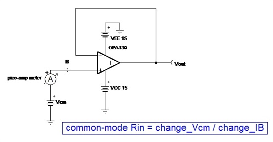
    In order to determine the common-mode input impedance of an op amp using pico-amp meter, you need to have at least two distinct points of Vcm and IB.  Use an input voltage source to change the Vcm (non-inverting input for follower configuration) appropriately to the OPA130 power supplies so it does not violate its common-mode input voltage range: (V-) +2V to (V+) - 2V and take two measurements (see setup below): for example, IB_1 @ Vcm=-10V and IB_2 @ Vcm=10V for +/-15V supplies; then Rin = 20V/(IB_2 - IB_1).  Keep in mind that most macro-models including OPA130 does NOT simulate the change of IB with Vcm characteristic of the op amp.